Intrasonic Technology V510 Installation And Operation Instructions Manual Download Page 17

31

32

Remote access to the IP video door phone is carried out over the Internet. In the local area

network, the IP address of the client-side computer must be in the same network segment that

the IP address of the IP video door phone. In the wide area network, the only requirement is

that the two sides can visit the public network and connect to the Internet through the IP

address or the dynamic domain name. The following will mainly focus on connecting and

setting up the local area network.

: Right-click on “Network Neighborhood” and click “Properties” in the menu to open the

“Network Connections” menu. Alternatively, if the operating system being used does not have

a “Network Neighborhood” icon, enter the Control Panel found in the “Start” menu; then, click

“Network and Internet”, and select “Network and Sharing

Center.” On the “Network and Sharing Center” page, there

should be a “Network” section; in that section, there should be

a “View Status” link next to a listing that reads “Connection:

Local Area Connection.” Click the “View Status” link. A small

“Local Area Connection Status” window will appear; at the

bottom of this screen, click “Properties”, and if prompted to

give permission to continue, click “Yes.”

: Double-click to open “Local Area Connection” from the

“Network Connections” menu.

: Click “Properties” in the lower-left corner of the window

(see preceding figure).

: Double-click “Internet protocol (TCP/IP)” from the “This

connection uses the following items” list in the center of the

window (see preceding figure).

Step 1

Step 2

Step 3

Step 4

3.3 Connection Settings

Step 5
Step 6

: Examine the IP address, subnet mask, and default gateway on the PC.
: Set the corresponding IP address, subnet mask, and default gateway on the indoor

unit(for detailed instructions, refer to

). If the subnet mask and

default gateway on the indoor unit are the same as those of the computer, then the IP address

Section 2.4.2 Network Setup

is most likely in the same network segment. However, they must not be exactly the same as
the ones on the indoor unit, as this will cause IP address conflicts. Taking the preceding figure
as an example, the IP address should be: 192.168.1.X, where X cannot be 244 or 1 (including
other IP addresses currently being used), and cannot exceed 255, as the subnet mask is
255.255.255.0, and the gateway is 192.168.1.1.

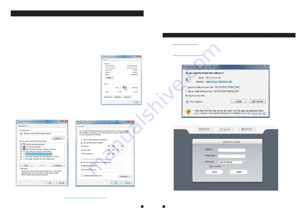
3.4 Control Download and Installation

After the aforementioned settings have been adjusted and saved, open the Internet browser,
enter

(192.168.1.X is the set IP address of the indoor unit) and confirm. If

the http port of indoor unit setting has been changed (if it is not “80”), it will be necessary to
add a “:” followed by a port number. For example, assuming that the current port number is “P”,
enter “

”, to correct the problem.

After connecting to the internet, Internet Explorer (or other Internet browser being used) will
automatically download the file to the computer as follows. Click “Install”.

http://192.168.1.X

http://192.168.1.X:P

The system will automatically enter the GUI as follows.

Select the English interface from the upper left side. Enter the correct password if a password
has been enabled. The password is the same as the one set in indoor unit.

: In this field, enter the username. The default is

.

[USER ID]

Admin

Summary of Contents for V510

Page 1: ...10 Display Series INSTALLATIONAND OPERATION INSTRUCTIONS 4 WireIPAHDVideoDoorPhone UserManual V510 Smartphone Video Doorbell ...

Page 2: ...0 before any attempt to dismantle the product Any attempts to dismantle the product will void the warranty An RMA Returned Material Authorization will be required prior to returning a product to Intrasonic Technology Inc To obtain an RMA call our toll free number 877 435 0670 and speak with a customer service representative All products returned to Intrasonic Technology without an RMA will be refu...

Page 3: ...4 2 1 Door Setting Basic 19 2 4 2 2 Door Setting Ring 19 2 4 3 Network 20 2 4 3 1 Network Basic 20 2 4 3 2 Network Port 20 2 4 3 3 Network Advanced 21 2 4 4 Record Scheduling 23 2 4 5 Alarm 24 2 4 6 Maintenance 25 2 4 6 1 SD 25 Table of Contents Table of Contents 3 4 2 4 10 Save Exit 29 3 Web Browser Operation 30 3 1 Feature 30 3 2 Network Security Setting 30 5 Operation Interface 33 3 5 1 Live 33...

Page 4: ...monitor Effective distance f Transmission 28m 4x0 2mm Transmission 50m 4x0 3mm Transmission 80m 4x0 5mm 2 2 2 Wire connection according to the following to avoid interference Power Video Audio GND GND Audio Power Video Indoor Monitor 1 pcs Screw Anchors 4 pcs Wall Screws 4 pcs Bracket 1 pcs 4 Pin Line 5 pcs This Quick Guide 1 pcs External Switching Power Adapter Optional 1 pcs USB Mouse Optional 1...

Page 5: ... supply DC 12V VIDEO AUDIO DATA GND VIDEO AUDIO DATA GND Indoor monitor slave Internet Network VIDEO DC 12V AC DC power adapter for camera not included DC 12V AC DC power adapter for camera not included CAM1 IP Indoor Monitor Main DOOR2 DOOR1 Speparate power supply AC DC power adapter for lock not included AC DC power adapter for lock not included Lock not included Screw anchors Bracket Connection...

Page 6: ...on the screen release the door lock Standby mode Press the button on indoor monitor unlock Press the button on indoor monitor again Hang up End The Visitor press the button on outdoor camera 2 call Both the visitor s voice and image will be not switched off within 20s of time span when the button is pressed unlock Start conversation with outdoor camera Press the button talking The indoor unit will...

Page 7: ...r camera When you are transferring a call to other extension the original conversation indoor unit will return to standby mode A continuous Ding Dong tone is heard To release door lock end conversation please page 10 as reference refer to NOTICE Press t on he button any of indoor units talking Outdoor camera call indoor monitor and conversation is underway NOTICE INTERNAL COMMUNICATION AMONG INDOO...

Page 8: ...icking left mouse key In live view or video playback double clicking will maximize the screen Mouse Drag In the motion detection setting interface you can left click and then drag the frame to set the motion detection area 1 Users can use a mouse or press buttons on the front panel to operate the device 2 In standby mode press the button to bring up the menu tool bar move the cursor to select menu...

Page 9: ... that is consistent with doorbells There are two options HD and D1 resolutions 2 4 1 1 System Basic HD Left click the file to enter the playback menu It will play the video from a single channel in full screen view When the selected files finish the screen will return to the file list menu Clicking button to enter into the first page clicking button to previous clicking button to the next page and...

Page 10: ...nnel Chroma Brightness Contrast Saturation Horizontal 1 31 31 31 31 31 Record Click to enter the Record menu to set up Resolution and Frame rate for every channel Record Channel All Resolution D1 Frame rate 25 Resolution This indicates the setup resolution and code rate for recording There are two options D1 and CIF resolutions The recording resolution of all channels can only be adjusted synchron...

Page 11: ...utdoor doorbell calls and alerts will be silenced during the period time of the No Disturbing mode Door Setting Basic Ring Video Close 00 00 00 00 Call REC Do not disturb mode DND mode schedule 2 4 3 Network Move the cursor to the Network icon and left click to enter the Network menu Network setup includes Basic Setup Port and Advanced Network Basic Port Advanced Network type Mac address IP addres...

Page 12: ...e AES and TKIP Input the password of the wireless router Click to save restart the indoor device manually and the wireless function of the device will take effect Web Port Setup Port Sets up a Web browser port via HTTP The default port number is 8090 but the specific number is model dependent If Administrator changes the Web port for example 8088 the port number should be added after the IP addres...

Page 13: ... until 10 00 PM on Tuesdays Wednesdays Thursdays and Fridays the process would be as follows Click the orange box at the bottom of the screen to select MD record Then in the row of gray boxes next to the TUE box click all of boxes from the third box from the left to the box under the 12 at the top of the timeline the box directly under the 12 should be selected in order to select the hours between...

Page 14: ...Auto overwrite This field indicates amount of space available and the amount of unused space available on the SD card The capacity of the SD can be used up to 128GB Indicates remaining recording time on the SD card There are two available statuses OK and No SD If a new SD card is used with the device for the first time please format the SD card Move the cursor to select the device to be formatted ...

Page 15: ...easons before a new password can be set it is necessary to enter the original password Modify PSW test Old password New password Confirm password Local Remote Local Permission This allows the Administrator to give each user its permission to access a unique set of indoor monitor functions That is the Administrator can give a user access to one some or all of the following functions Record Playback...

Page 16: ...N It also supports IP and domain name visiting To ensure reliable remote viewing of IVR footage it is highly recommended that users have either Windows XP Windows 7 or Windows 8 installed on their computers and that they use either Internet Explorer 6 0 Internet Explorer 7 0 Internet Explorer 8 0 Internet Explorer 9 0 Mozilla Firefox or Google Chrome as their Internet browser In the appendix there...

Page 17: ...tep 2 Step 3 Step 4 3 3 Connection Settings Step 5 Step 6 Examine the IP address subnet mask and default gateway on the PC Set the corresponding IP address subnet mask and default gateway on the indoor unit for detailed instructions refer to If the subnet mask and default gateway on the indoor unit are the same as those of the computer then the IP address Section 2 4 2 Network Setup is most likely...

Page 18: ...rease image contrast This indicates that the channel has detected motion while in motion detection mode of the remote indoor unit Unlock for the door machine Click this button to access the Unlock window shown as below input the correct password and click the button to confirm To use the controls move the cursor over the icons which will become highlighted when selected Connect all windows or disc...

Page 19: ...3 11 15 05 CAM2 Using this button users can download files to their computers and save them to a HDD for backup or later viewing The downloaded file format is AVI The option on the left side of the file is available for downloading indicates the file will be saved to a HDD after clicking the button Single Frame Click Remote Setting to enter the Remote Setting setup menu This interface includes rec...

Page 20: ... enter the Mobile Settings interface From this page users can set ports push switch and push time G System Info Version Information From the sidebar on the left click System INFO and then select Version INFO to enter the system information interface Here users can find out the device name software version and the release date H REMOTE UPGRADE From the sidebar on the left click REMOTE UPGRADE to en...

Page 21: ...ownloaded via APP Store In APP Store or Play Store please search for MobileEyeDoor Please see the instruction manual for your mobile to install the program 3 5 8 logout 4 1 Iphone Mobile or Ipad The Apple iPhone or iPad application like all iPhone or iPad applications needs to be downloaded directly from the App Store Open APP store search for MobileEyeDoor it s a free application 2 1 2 uCareHome ...

Page 22: ...version 7 0 517 36 as an example After installing Google Chrome search for the IE TAB Chrome add on this file is named extension_1_4_30_4 crx This file can be downloaded from the Chrome Web Store Open Chrome enter the IP address of the indoor unit into address bar and the following screen will appear 4 Drag the add on into the browser interface and the following screen will appear Appendix 2 Acces...

Page 23: ... ll see the Compatibility View button in the Address bar You can only turn on Compatibility View in Internet Explorer for the desktop See if the Compatibility View button appears in the Address bar If you don t see the button there s no need to turn on Compatibility View Tap or click the Compatibility View button to display the site in Compatibility View Once you turn on Compatibility View Interne...

Reviews: