


UH179TW
/
UH679TW
UDH179-02
23
T
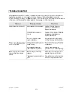
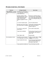
ROUBLESHOOTING
HSD 2000-ET II Mirror Tape Heads are fabricated with high quality components that provide
trouble-free operation for a long period of time. However, should a problem occur, we
recommend that you consult the following table. If the problem you encounter is not discussed
in this table, call Interpack Technical Support. (See page 4 of this document).
T
ROUBLE
P
OSSIBLE
C
AUSES
S
OLUTIONS
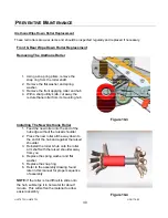
Tape does not cut cleanly.
Blade needs to be replaced.
Knife spring too weak or
broken
One way clutched roller
needs adjusting
Replace blade. Refer to
preventive maintenance
section for details
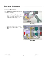
Replace knife spring. Refer to
preventive maintenance
section for details
Slightly increase the tension
on the one way clutched roller
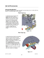
Tape Leg
UUU
in the tape head
UUU
folds up on itself
Strong air circulation (fan) is
in the vicinity
Spring loaded tape leg
stiffener is out of position
Redirect airflow away from the
tape head
Gently bend forward to
provide a curve in the tape leg
Back tape leg does not fit
tight on the box. (ripple
effect)
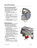
Main spring is not strong
enough
Tape applying tension is too
great
Change for the stronger main
spring. (Part no. UPH3817)
Re-set tension on the mandrel
and one way clutched roller
Summary of Contents for HSD2000-ET II MIRROR
Page 1: ...HSD2000 ET II MIRROR Serial Numbers H179 or H679 XX X XXX TAPE HEAD ...
Page 2: ...UH179TW UH679TW UDH179 02 2 ...
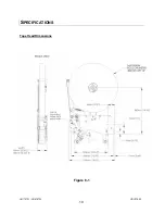
Page 10: ...UH179TW UH679TW UDH179 02 10 SPECIFICATIONS UUUTape Head Dimensions Figure 6 1 ...
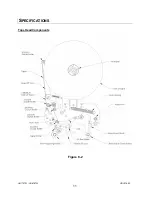
Page 11: ...UH179TW UH679TW UDH179 02 11 SPECIFICATIONS UUUTape Head Components Figure 6 2 ...
Page 41: ...41 THIS PAGE INTENTIONALLY BLANK ...
Page 42: ...6 12 3 4 8 9 1 10 11 2 5 7 42 ...
Page 44: ...7 8 9 11 6 12 7 8 7 8 9 10 3 5 2 4 1 44 MAIN FRAME ...
Page 46: ...1 2 3 4 5 46 FRONT COVER FRAME ...
Page 48: ...3 5 6 4 1 2 48 REAR COVER FRAME ...
Page 50: ... 50 REAR ARM ...
Page 52: ...11 1 15 13 14 10 2 4 5 6 9 12 8 2 3 7 13 13 10 8 CLUTCH ASSEMBLY ...
Page 54: ... 54 MANDREL ASSEMBLY ...
Page 56: ... 56 PEEL OFF ARM ASSEMBLY ...
Page 58: ... 58 LINK ASSEMBLY ...
Page 60: ...18 13 17 15 4 3 12 14 16 9 8 7 7 9 3 6 10 5 11 1 2 5 19 20 60 FRONT ARM ...
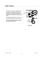
Page 62: ...1 8 9 4 7 6 9 5 2 10 3 11 62 TAPE SHOE ASSEMBLY ...
Page 64: ... 64 KNIFE ARM ...
Page 66: ... 66 REPULSIVE PIVOT ASSEMBLY ...


