UH179TW
/
UH679TW
UDH179-02
22
S
ET
-U
P
P
ROCEDURES
UUU
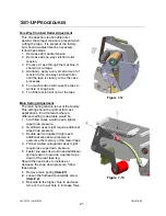
Mandrel Tension Adjustment
Mandrel tension is required to control over spin
of a full tape roll after the case is finished
processing. The tension is set at the factory
and no change to the tension should be
necessary since the peel off roller should
control the over spin in most cases.
Do not increase mandrel tension to improve
tape cutting. Slightly increase the one way
clutched roller to improve cutting action
Changes in mandrel tension might be required
for the following reasons:
1. Larger than 1000yd (914m) are used.
2. Tape head is installed on faster line
speeds.
3. The tape roll continues to over spin
more than ¼ turn after the case leaves
the tape head.
Should a change in mandrel tension be
required, follow these steps:
1. Observe the rotation of a full tape roll as
a case processes.
2. Should the tape roll continue to rotate
more than ¼ turn after the case leaves
the tape head, increase the adjustment
nut slightly until only a small amount of
rotation occurs.
3. Should the tape roll rotate very little or
not at all after the case leaves the tape
head, decrease the adjustment nut
slightly until a small amount of rotation
occurs.
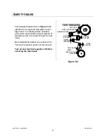
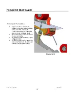
Figure 7-14
Summary of Contents for HSD2000-ET II MIRROR
Page 1: ...HSD2000 ET II MIRROR Serial Numbers H179 or H679 XX X XXX TAPE HEAD ...
Page 2: ...UH179TW UH679TW UDH179 02 2 ...
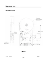
Page 10: ...UH179TW UH679TW UDH179 02 10 SPECIFICATIONS UUUTape Head Dimensions Figure 6 1 ...
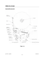
Page 11: ...UH179TW UH679TW UDH179 02 11 SPECIFICATIONS UUUTape Head Components Figure 6 2 ...
Page 41: ...41 THIS PAGE INTENTIONALLY BLANK ...
Page 42: ...6 12 3 4 8 9 1 10 11 2 5 7 42 ...
Page 44: ...7 8 9 11 6 12 7 8 7 8 9 10 3 5 2 4 1 44 MAIN FRAME ...
Page 46: ...1 2 3 4 5 46 FRONT COVER FRAME ...
Page 48: ...3 5 6 4 1 2 48 REAR COVER FRAME ...
Page 50: ... 50 REAR ARM ...
Page 52: ...11 1 15 13 14 10 2 4 5 6 9 12 8 2 3 7 13 13 10 8 CLUTCH ASSEMBLY ...
Page 54: ... 54 MANDREL ASSEMBLY ...
Page 56: ... 56 PEEL OFF ARM ASSEMBLY ...
Page 58: ... 58 LINK ASSEMBLY ...
Page 60: ...18 13 17 15 4 3 12 14 16 9 8 7 7 9 3 6 10 5 11 1 2 5 19 20 60 FRONT ARM ...
Page 62: ...1 8 9 4 7 6 9 5 2 10 3 11 62 TAPE SHOE ASSEMBLY ...
Page 64: ... 64 KNIFE ARM ...
Page 66: ... 66 REPULSIVE PIVOT ASSEMBLY ...

