


Section 9, Installing the Distribution Module
•
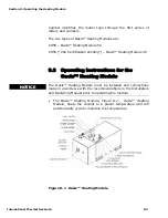
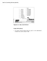
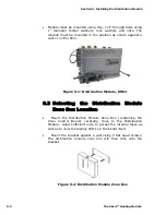
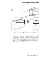
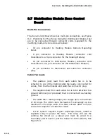
Module must be mounted using four, 1/4” through bolts using
1” diameter fender washers, lock washers and nuts. The
module must be mounted in the position as shown against a
wall or on the floor.
Figure 9-1: Distribution Module, DM12
9.3 Selecting the Distribution Module
Zone Box Location
•
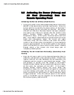
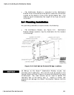
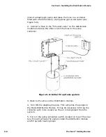
Mount the Distribution Module Zone Box (containing the
Zone Control Board) vertically, close to the Distribution
Module. Allow sufficient room to access the internal fuses as
well as to view the display LED’s on the board itself.
•
Mount the bracket against a wall using 2 flat head screws.
The distribution module zone box will then click onto the
bracket.
Figure 9-2: Distribution Module Zone Box
9-2
The Oasis™ Heating Module
Summary of Contents for Diesel and AC Heating System for Recreational Vehicles and Yachts
Page 14: ...Section 1 Overview 1 8 The Oasis Heating Module...
Page 20: ...Section 2 Mounting the Oasis Heating Module 2 6 The Oasis Heating Module...
Page 28: ...Section 3 Installing the Exhaust System 3 8 The Oasis Heating Module...
Page 32: ...Section 4 Installing the Fuel System 4 4 The Oasis Heating Module...
Page 41: ......
Page 48: ...Section 7 Plumbing the System 7 6 The Oasis Heating Module...
Page 73: ......
Page 74: ...9...
Page 75: ...6 6 6 6 7K 8 0 7 4 7 4 7 8 9 7 8 9 7 8 9 7 8 9 D B 15C 8 D D H D 13 C 8 B B EC 8 D...
Page 76: ...Section 9 Installing the Distribution Module 9 14 The Oasis Heating Module...