Section 8, Operating the Heating Module
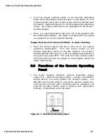
Activating the Burner and AC immersion Element(s)
Jointly
•
Turn the burner switch ON and place the AC power switch on
the Remote Operating Panel to either the one element or two
element position. The Burner and AC Heat (green) LED’s will
turn ON indicating the diesel burner and AC element(s) have
been selected.
8.6 Activating the Cabin Fan Heaters
through the Thermostats
(Distribution Module Equipped Systems Only) (Burner or
AC Heat or Engine Heat Source Available)
•
Any thermostat connected to the Distribution Module’s Zone
Control Board and calling for heat will cause the cabin fan
controlled by that thermostat to be enabled. The ITR cabin
fan has a built-in aquastat that prevents the cabin fan from
blowing cold air. Once the room temperature has reached the
temperature called for by the thermostat the cabin fan will
turn off.
8.7 Activating the Domestic Hot Water
(Oasis™ Heating Module and Distribution Module used in
Tandem) (Burner or AC Heat On)
•
As long as heat is available in the Oasis™ Heating Module, the
Distribution Module (Optional) will respond to a call for
domestic hot water. Ensure that a heat source has been
selected (i.e. Burner, AC, Engine). The production of the
domestic hot water is continuous on the Burner operation
and limited when using AC or Engine.
The domestic water pump is not a part of, nor controlled by the
Distribution Module or The Oasis™ Heating Module.
NOTICE
8.8 Activating Engine Heat & Pre-heat
(Oasis™ Heating Module and Distribution Module used in
Tandem) (Burner or AC Heat On)
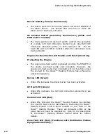
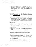
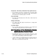
Pre-heating the Engine
8-6
The Oasis™ Heating Module
Summary of Contents for Diesel and AC Heating System for Recreational Vehicles and Yachts
Page 14: ...Section 1 Overview 1 8 The Oasis Heating Module...
Page 20: ...Section 2 Mounting the Oasis Heating Module 2 6 The Oasis Heating Module...
Page 28: ...Section 3 Installing the Exhaust System 3 8 The Oasis Heating Module...
Page 32: ...Section 4 Installing the Fuel System 4 4 The Oasis Heating Module...
Page 41: ......
Page 48: ...Section 7 Plumbing the System 7 6 The Oasis Heating Module...
Page 73: ......
Page 74: ...9...
Page 75: ...6 6 6 6 7K 8 0 7 4 7 4 7 8 9 7 8 9 7 8 9 7 8 9 D B 15C 8 D D H D 13 C 8 B B EC 8 D...
Page 76: ...Section 9 Installing the Distribution Module 9 14 The Oasis Heating Module...


