4.1.6
Bias Selection
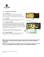
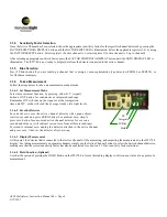
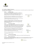
On the ILT1700, Press 5V Bias button if you are reading a channel that is using a vacuum photodiode type detector (SED240
or SED220), or for flash measurements. It is recommended not to scan a combination of vacuum photodiode type detectors with
other detector types that do not require the 5V Bias.
4.1.7
Taking a Measurement
Follow the steps below to take a measurement using SOFTDAQ software.
4.1.7.1 Zero the Detectors
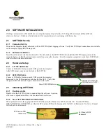
For a dark zero, cover all selected channel detector(s) with opaque object,
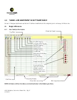
wait ten seconds and click the ZERO function button (see Section 4.1.1).
For ambient zero, simply press ZERO function button for all uncovered selected
channel detector(s) for over one second and release. (will subtract current zero
from all future readings) To return to internal zero, unplug the detector attached
to the active channel and press ZERO function button.
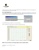
NOTE: After initial software bootup, the user will not be able to start scanning data without first performing the ZERO
function. User will be prompted with a dialog box stating that the system must be zero'd prior to starting a scan
4.1.7.2 Set Measurement Mode
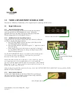
Select measurement function by pressing either D.C. (signal) function
button or Integrate function button for continuous or integrated readings
from user interface in Section 4.1.1. Remember Integrate mode will sum
up the signal over that integration time and D.C. mode will read the average
steady state light levels
.
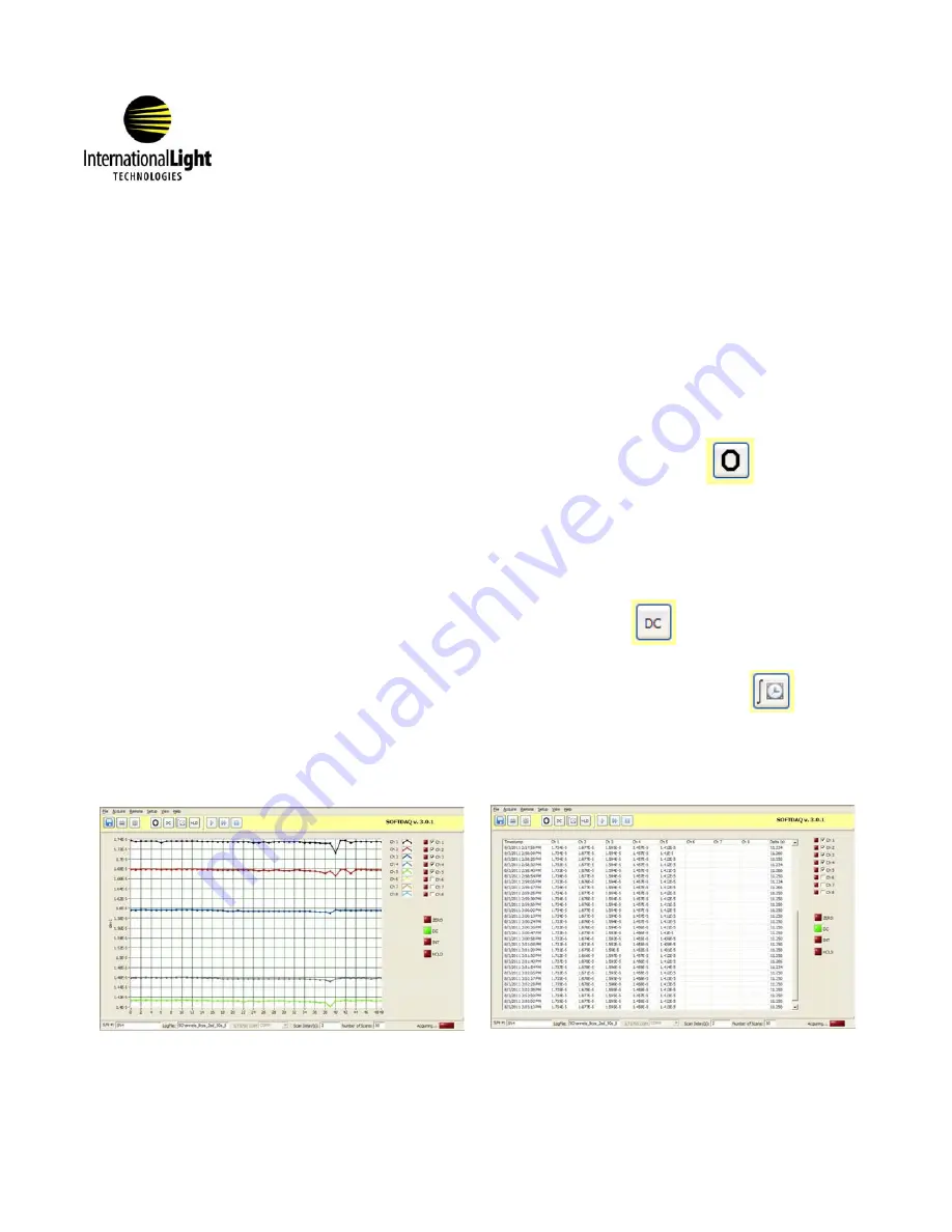
4.1.7.3 Data Display Options
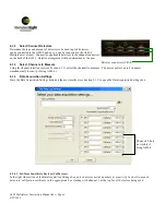
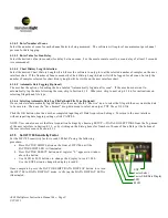
In the Top Menu (see Section 4.1.1), select VIEW and choose the desired view for measurement readings. User has the option of
viewing the CHART, which plots the values in an auto-populated graph, or viewing a TABLE which auto-populates the table with the
measurements for each channel during a scan.
A803 Multiplexer Instruction Manual Rev -
Page 10
9/22/
2011
ZERO Function
DC Function
Integrate Function
Example CHART view
Example TABLE view


