


14
513 01 3402 02
FIGURE 13
Phase Monitor Control and LED Indicators
LED
STATUS
OFF
No Call for compressor operation
FLASHING
Reversed phase
ON
Normal
Checking and Adjusting Refrigerant Charge
The refrigerant system is fully charged with R
−
410A refrigerant
and is tested and factory sealed.
NOTE
: Adjustment of the refrigerant charge is not required
unless the unit is suspected of not having the proper R
−
410A
charge.
A superheat charging chart is attached to the inside of the
compressor access panel (see FIGURE 16). The chart includes
the required suction line temperature at given suction line
pressures and outdoor ambient temperatures.
An accurate thermocouple
−
or thermistor
−
type thermometer,
and a gauge manifold are required when using the superheat
charging method for evaluating the unit charge. Do not use
mercury or small dial
−
type thermometers because they are not
adequate for this type of measurement.
NOTE
: Allow system to operate for a minimum of 15 minutes
before checking or adjusting refrigerant charge.
IMPORTANT
: When evaluating the refrigerant charge, an
indicated adjustment to the specified factory charge must always
be very minimal. If a substantial adjustment is indicated, an
abnormal condition exists somewhere in the cooling system,
such as insufficient airflow across either coil or both coils.
Proceed as follows:
1. Remove cap from low pressure service fitting.
2. Using hoses with valve core depressors, attach low pres-
sure gauge hose to low pressure service fitting.
3. Start the unit in cooling mode and let run until system
pressures stabilize.
4. Measure and record the following:
a. Outdoor ambient
−
air temperature (
°
C) db.
b. Evaporator inlet
−
air temperature (
°
C) wb.
c. Suction
−
tube temperature (
°
C) at low
−
side service
fitting.
d. Suction (low
−
side) pressure (kPA).
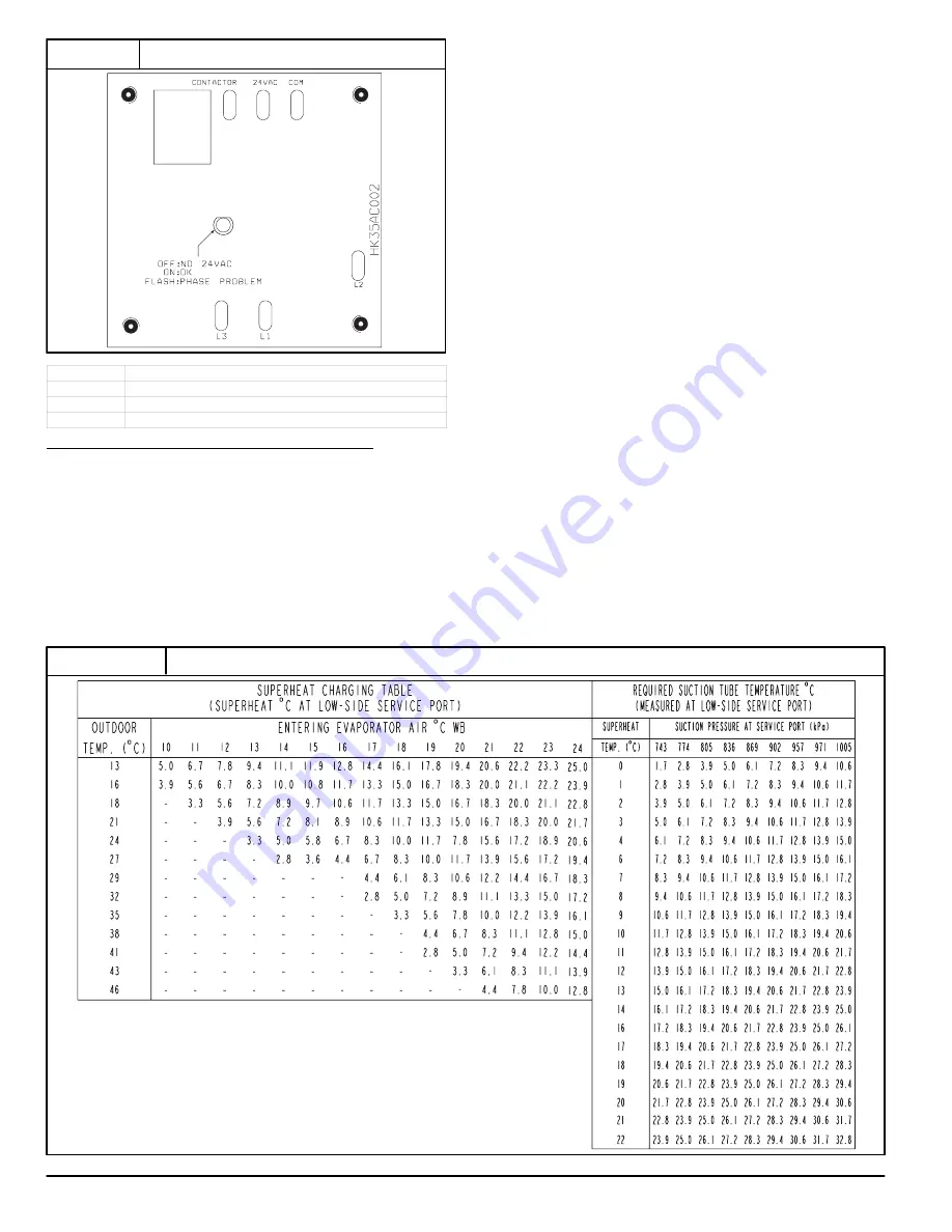
5. Using “Cooling Charging Tables” compare outdoor
−
air
temperature (
°
C) db with the entering evaporator air
temperature (
°
C) wb to determine desired superheat
temperature. (See FIGURE 14).
6. Using the superheat value in step 5, locate the intersec-
tion of the required superheat with the suction pressure
previously measured. Note the required suction tube
temperature. Using a tolerance of +/
−
(1.7
°
C), add refri-
gerant if actual temperature is higher than charted suction
tube temperature, or remove refrigerant if actual temper-
ature is lower than charted suction tube temperature.
NOTE
: If the problem causing the inaccurate readings is a
refrigerant leak, refer to Check for Refrigerant Leaks section.
FIGURE 14
Cooling Charging Table
−
Superheat
50ES500443 - 2.0