


428 01 9702 01
3
Specifications subject to change without notice.
Operating Ambient
Minimum outdoor operating ambient in cooling mode is 55
_
F
(13
_
C), maximum 125
_
F (52
_
C).
Rigging
PERSONAL INJURY AND/OR EQUIPMENT
DAMAGE HAZARD
Failure to follow this caution may result in personal injury
and/or equipment damage.
Be sure unit panels are securely in place prior to rigging.
CAUTION
!
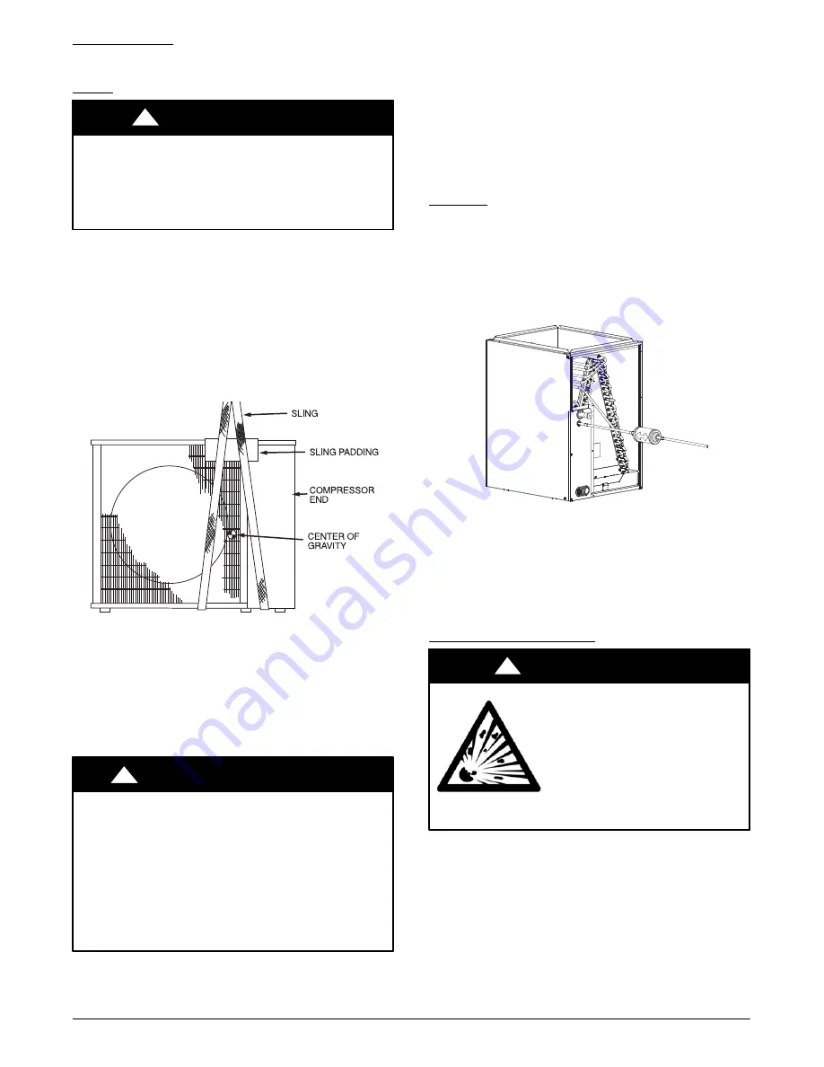
Keep the unit upright and lift unit using a sling. Use cardboard or
padding under the sling, and spreader bars to prevent sling damage
to the unit. See Fig. 3. Install the unit so that the coil does not face
into prevailing winds. If this is not possible and constant winds
above 25 mph are expected, use accessory wind baffle. See
installation instructions provided with the accessory kit.
NOTE
: Accessory wind baffles should be used on all units with
accessory low ambient temperature control.
Field
−
fabricated snow or ice stands may be used to raise unit when
operation will be required during winter months. Units may also be
wall mounted using the accessory wall mounting kit.
A07396
Fig. 3
-
Lifting Unit with Sling
COMPLETE REFRIGERANT PIPING
CONNECTIONS
Outdoor units may be connected to indoor units using
field
−
supplied tubing of refrigerant grade and condition. See
Specification Sheet for correct line sizes. Do not use less than 10 ft
(3.05 m) of interconnecting tubing.
CAUTION
!
UNIT DAMAGE HAZARD
Failure to follow this caution may result in equipment
damage or improper operation.
If any section of pipe is buried, there must be a 6 in. (152.4
mm) vertical rise to the valve connections on the outdoor
unit. If more than the recommended length is buried,
refrigerant may migrate to cooler, buried section during
extended periods of system shutdown. This causes refrigerant
slugging and could possibly damage the compressor at
start
−
up.
When more than 80 ft (24.4 m) of interconnecting tubing and more
than 20 ft (6.1 m) of vertical lift is used, consult the residential
Long Line Application Guide for required accessories. If either
refrigerant tubing or indoor coil is exposed to the atmosphere, the
system must be evacuated following good refrigeration practices.
Run refrigerant tubes as directly as possible, avoiding unnecessary
turns and bends. Suspend refrigerant tubes so they do not damage
insulation on vapor tube and do not transmit vibration to structure.
Also, when passing refrigerant tubes through a wall, seal the
opening so that vibration is not transmitted to structure. Leave
some slack in refrigerant tubes between structure and outdoor unit
to absorb vibration. Refer to separate indoor unit installation
instructions for additional information.
Filter Drier
Refer to Fig. 4 and install filter drier as follows:
1. Braze 5 in. (127 mm) liquid tube to the indoor coil.
2. Wrap filter drier with damp cloth.
3. Braze filter drier to 5 in. (127 mm) long liquid tube from
step 1.
4. Connect and braze liquid refrigerant tube to the filter drier.
A05227
Fig. 4
-
Filter Drier Components
The filter drier must be replaced whenever the refrigeration system
is exposed to the atmosphere.
Only use factory specified liquid
−
line filter driers with rated
working pressures less than 600 psig.
NOTE
: Do not install a suction
−
line filter drier in liquid line.
Make Piping Sweat Connections
EXPLOSION HAZARD
Failure to follow this warning could
result in death, serious personal injury,
and/or property damage.
Never use air or gases containing
oxygen for leak testing or operating
refrigerant compressors. Pressurized
mixtures of air or gases containing
oxygen can lead to an explosion.
!
WARNING
Remove plastic caps from liquid and suction service valves. Use
refrigerant grade tubing. Service valves are closed from the factory
and are ready for brazing. After wrapping the service valve with a
wet cloth, the tubing set can be brazed to the service valve using
either silver bearing or non
−
silver bearing brazing material.
Consult local code requirements. Refrigerant tubing and the indoor
coil are now ready for leak testing.
NOTE
: Unit is shipped with R
−
410A refrigerant factory charge
indicated on nameplate.
Pass nitrogen or other inert gas through piping while brazing to
prevent formation of copper oxide.