


INSTALLATION INSTRUCTIONS
3-phase R-22 Split System Heat Pump
8
506 01 5001 00
H. EVACUATING LINE SET AND INDOOR COIL
The unit is shipped with a factory refrigerant charge. The
liquid line and suction line service valves have been
closed after final testing at the factory. Do not disturb
these valves until the line set and indoor coil have been
evacuated and leak checked, or the charge in the unit
may be lost.
NOTE:
Do not use any portion of the factory charge for
purging or leak testing. The factory charge is for filling the
system only after a complete evacuation and leak check
has been performed.
!
CAUTION
PRODUCT DAMAGE HAZARD
Failure to follow this caution may result in product
damage.
Never use the outdoor unit compressor as a vacu‐
um pump. Doing so may damage the compressor.
Line set and indoor coil should be evacuated using the
recommended deep vacuum method of 500 microns. If
deep vacuum equipment is not available, the alternate
triple evacuation method may be used by following the
specified procedure.
If vacuum must be interrupted during the evacuation
procedure, always break vacuum with dry nitrogen.
Deep Vacuum Method
The deep vacuum method requires a vacuum pump
capable of pulling a vacuum to 500 microns and a vacuum
gauge capable of accurately measuring this vacuum
level. The deep vacuum method is the most positive way
of assuring a system is free of air and water.
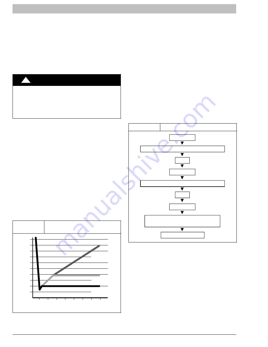
Watch the vacuum gauge as the system is pulling down.
The response of the gauge is an indicator of the condition
of the system (refer to Figure 9).
With no leaks in the system, allow the vacuum pump to
run for 30 minutes minimum at the deep vacuum level.
Figure 9
Deep Vacuum Gauge Response
and System Conditions
500
MINUTES
0
1
2
4
6
1000
1500
LEAK IN
SYSTEM
VACUUM TIGHT
TOO WET
TIGHT
DRY SYSTEM
2000
M
ICRONS
2500
3000
3500
4000
4500
5000
3
7
5
Triple Evacuation Method
The triple evacuation method should only be used when
system does not contain any water in liquid form and
vacuum pump is only capable of pulling down to 28 inches
of mercury. Refer to Fig. 10 and proceed is as follows:
1.
Pull system down to 28 inches of mercury and
allow pump to continue operating for an additional
15 minutes.
2.
Close manifold valves or valve at vacuum pump
and shut off vacuum pump.
3.
Connect a nitrogen cylinder and regulator to
system and fill with nitrogen until system pressure
is 2 psig.
4.
Close nitrogen valve and allow system to stand for
1 hour. During this time, dry nitrogen will diffuse
throughout the system absorbing moisture.
5.
Repeat this procedure as indicated in Figure 10.
6.
After the final evacuate sequence, confirm there
are no leaks in the system. If a leak is found, repeat
the entire process after repair is made.
Figure 10
Triple Evacuation Sequence
CHECK FOR TIGHT, DRY SYSTEM
(IF IT HOLDS DEEP VACUUM)
EVACUATE
BREAK VACUUM WITH DRY NITROGEN
WAIT
EVACUATE
CHARGE SYSTEM
BREAK VACUUM WITH DRY NITROGEN
EVACUATE
WAIT
I. OPENING SERVICE VALVES
Outdoor units are shipped with a refrigerant charge
sealed in the unit. Opening the service valves releases
this charge into the system.
NOTE:
Open the Suction service valve first. If the Liquid
service valve is opened first, oil from the compressor may
be drawn into the indoor coil TXV, restricting refrigerant
flow and affecting operation of the system.
Remove Suction service valve cap and insert a hex
wrench into the valve stem. Hold the valve body steady
with an end-wrench and back out the stem by turning the
hex wrench counterclockwise. Turn the stem until it just
contacts the rolled lip of the valve body.
After the refrigerant charge has bled into the system,
open the Liquid service valve.


