15
441 01 1411 04
Specifications are subject to change without notice.
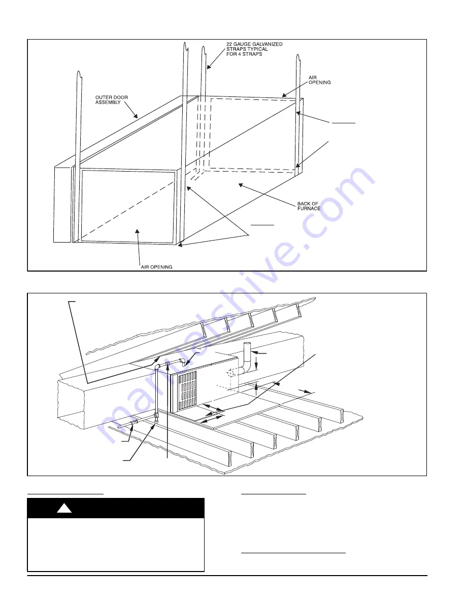
Figure 16
−
Horizontal Suspension with Straps
METHOD 2
USE (4) #8 x 3/4 (19 mm) SHEET
METAL SCREWS FOR EACH
STRAP. THE STRAPS
SHOULD BE VERTICAL
AGAINST THE FURNACE
SIDES AND NOT PULL AWAY
FROM THE FURNACE
SIDES.
METHOD 1
FOLD ALL STRAPS UNDER
FURNACE AND SECURE WTH
(4) #8 x 3/4 (19 mm) SHEET METAL SCREWS
(2 SCREWS IN SIDE AND 2 SCREWS
IN BOTTOM).
A10131
Figure 17
−
Typical Attic Installation
30-IN . (762mm)
MIN WORK AREA
6
″
M IN
*
TYPE-B
VENT
17
3
/
4
″
22
″
SHEET
MET AL
SEDIMENT
TRAP
EQUIPMENT MANU AL
SHUT -OFF GAS VA LV E
LINE CONT A CT ONL Y PERMISSIBLE BETWEEN
LINES FORMED BY INTERSECTIONS OF
THE T OP AND TW O SIDES OF THE FURNA CE
JA CKET AND BUILDING JOISTS ,
STUDS , OR FRAMING.
GAS
ENTR Y
17
3
/
4
″
(451mm)OVERALL
4
3
/
4
″
(121mm) UNDER DOOR
1
″
(25mm) UNDER FURNACE
EXTEND OUT 12
″
(305mm)
FR OM FA CE OF DOOR
* WHEN USED W ITH
SINGLE W ALL VEN T
CONNECTIONS
UNION
(152mm)
(451mm)
(559mm)
A10164
Return Air Connections
FIRE HAZARD
Failure to follow this warning could cause personal
injury, death and/or property damage.
Never connect return
−
air ducts to the back of the
furnace. Refer to the following instructions.
!
WARNING
Downflow Furnaces
The return
−
air duct must be connected to return
−
air opening
(bottom inlet) as shown in Figure 21. DO NOT cut into casing
sides (left or right). Side opening is permitted for only upflow
and most horizontal furnaces. (See Figure 21) Bypass
humidifier connections should be made at ductwork or coil
casing sides exterior to furnace.
Upflow and Horizontal Furnaces
The return
−
air duct must be connected to bottom, sides (left
or right), or a combination of bottom and side(s) of main


