International comfort products C4A3 Series Installation Instructions Manual Download Page 8

INSTALLATION INSTRUCTIONS

R-410A Split System Air Conditioner

8

421 01 5101 00

Deep Vacuum Method

The deep vacuum method requires a vacuum pump
capable of pulling a vacuum to 500 microns and a vacuum
gauge capable of accurately measuring this vacuum
level. The deep vacuum method is the most positive way
of assuring a system is free of air and water.

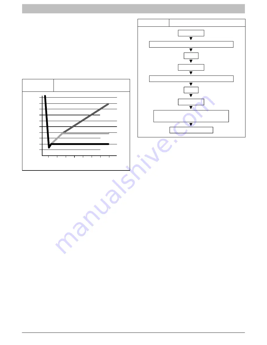
Watch the vacuum gauge as the system is pulling down.
The response of the gauge is an indicator of the condition
of the system (refer to Figure 6).

With no leaks in the system, allow the vacuum pump to
run for 30 minutes minimum at the deep vacuum level.

Figure 6

Deep Vacuum Gauge Response

and System Conditions

500

MINUTES

0

1

2

4

6

1000

1500

LEAK IN
SYSTEM

VACUUM TIGHT
TOO WET

TIGHT
DRY SYSTEM

2000

M

ICRONS

2500

3000

3500

4000

4500

5000

3

7

5

Triple Evacuation Method

The triple evacuation method should only be used when
system does not contain any water in liquid form and
vacuum pump is only capable of pulling down to 28 inches
of mercury. Refer to Fig. 7 and proceed is as follows:

1.

Pull system down to 28 inches of mercury and
allow pump to continue operating for an additional
15 minutes.

2.

Close manifold valves or valve at vacuum pump
and shut off vacuum pump.

3.

Connect a nitrogen cylinder and regulator to
system and fill with nitrogen until system pressure
is 2 psig.

4.

Close nitrogen valve and allow system to stand for
1 hour. During this time, dry nitrogen will diffuse
throughout the system absorbing moisture.

5.

Repeat this procedure as indicated in Figure 7.

6.

After the final evacuate sequence, confirm there
are no leaks in the system. If a leak is found, repeat
the entire process after repair is made.

Figure 7

Triple Evacuation Sequence

CHECK FOR TIGHT, DRY SYSTEM

(IF IT HOLDS DEEP VACUUM)

EVACUATE

BREAK VACUUM WITH DRY NITROGEN

WAIT

EVACUATE

CHARGE SYSTEM

BREAK VACUUM WITH DRY NITROGEN

EVACUATE

WAIT

I. OPENING SERVICE VALVES

Outdoor units are shipped with a refrigerant charge
sealed in the unit. Opening the service valves releases
this charge into the system.

NOTE:

 Open the Suction service valve first. If the Liquid

service valve is opened first, oil from the compressor may
be drawn into the indoor coil TXV, restricting refrigerant
flow and affecting operation of the system.

Remove Suction service valve cap and insert a hex
wrench into the valve stem. Hold the valve body steady
with an end-wrench and back out the stem by turning the
hex wrench counterclockwise. Turn the stem until it just
contacts the rolled lip of the valve body.

After the refrigerant charge has bled into the system,
open the Liquid service valve.

NOTE:

 These are not back-seating valves. It is not

necessary to force the stem tightly against the rolled lip.

The service valve cap is a primary seal for the valve and
must be properly tightened to prevent leaks. Make sure
cap is clean and apply refrigerant oil to threads and
sealing surface on inside of cap.

Tighten cap finger tight and then tighten additional 

 of a

turn (1 wrench flat) to properly seat the sealing surfaces.

J. GAUGE PORTS

Check for leaks at the schrader ports and tighten valve
cores if necessary. Install plastic caps finger tight.

Summary of Contents for C4A3 Series

Page 1: ...following manner The signal word CAUTION is used throughout this manual in the following manner Signal Words on Product Labeling Signal words are used in combination with colors and or pictures on product labels WARNING Safety Labeling and Signal Words CAUTION WARNING TABLE OF CONTENTS Inspect New Unit 2 Safety Considerations 2 Location 2 Clearances 2 3 Unit Support 4 Refrigeration System 5 8 Elec...

Page 2: ...kes vents or bedroom windows Noise may carry into the openings and disturb people inside Locate unit in a well drained area or support unit high enough so that water runoff will not enter the unit Locate unit away from areas where heat lint or exhaust fumes will be discharged onto unit as from dryer vents Locate unit away from recessed or confined areas where recirculation of discharge air may occ...

Page 3: ...stem Air Conditioner 421 01 5101 00 3 Figure 1 Clearances various examples Wall 6 24 Service Wall Wall Wall 6 6 Post Wall Wall 18 18 18 18 6 6 6 18 18 18 18 24 Service 24 Service 24 Service 24 Service 24 Service 24 Service 4 4 wide fence 18 18 ...

Page 4: ...f level Place the unit over one or more load bearing walls If there are several units mount them on platforms that are self supporting and span several load bearing walls These suggestions are to minimize noise and vibration transmission through the structure If the structure is a home or apartment avoid locating the unit over bedrooms or study NOTE When unit is to be installed on a bonded guarant...

Page 5: ...al TXV installation is shown in Figure 3 Figure 3 Typical TXV Installation TXV SENSING BULB EQUALIZER TUBE ÉÉ ÉÉ ÉÉ ÉÉ 8 O CLOCK 4 O CLOCK STRAP SENSING BULB EITHER SIDE SUCTION TUBE INDOOR COIL SUCTION TUBE LIQUID TUBE B REFRIGERANT LINE SETS The refrigerant line set must be properly sized to assure maximum efficiency and proper oil circulation Refer to Product Specifications and Long Line Applic...

Page 6: ...n improp er product operation Do not leave system open to atmosphere any lon ger than absolutely required for installation Inter nal system components especially refrigerant oils are extremely susceptible to moisture con tamination Keep ends of tubing sealed during installation until the last possible moment Figure 4 Routing and Suspending Refrigerant Lines INSULATION SUCTION TUBE LIQUID TUBE OUTD...

Page 7: ...ve and joint Wrap service valves with a heat sinking material such as a wet cloth Braze joints using a Sil Fos or Phos copper alloy CAUTION PRODUCT DAMAGE HAZARD Failure to follow this caution may result in product damage Braze with Sil Fos or Phos copper alloy on cop per to copper joints and wrap a wet cloth around rear of fitting to prevent damage to TXV H EVACUATING LINE SET AND INDOOR COIL The...

Page 8: ...oisture 5 Repeat this procedure as indicated in Figure 7 6 After the final evacuate sequence confirm there are no leaks in the system If a leak is found repeat the entire process after repair is made Figure 7 Triple Evacuation Sequence CHECK FOR TIGHT DRY SYSTEM IF IT HOLDS DEEP VACUUM EVACUATE BREAK VACUUM WITH DRY NITROGEN WAIT EVACUATE CHARGE SYSTEM BREAK VACUUM WITH DRY NITROGEN EVACUATE WAIT ...

Page 9: ...ine Voltage connections with raintight conduit and fittings Most codes require a disconnect switch outdoors within sight of the unit Consult local codes for special requirements Route electrical supply Line Voltage wiring through knockout hole in bottom of Control Box Connect wires to Contactor and Ground Lug according to Wiring Diagram on unit Refer to Figure 8 Route thermostat wiring through rub...

Page 10: ... THERMOSTAT FURNACE Y G W HEAT STAGE 1 COOL STAGE 1 INDOOR FAN AIR CONDITIONER 24 VAC HOT 24 VAC COM R C G W W1 Y Y2 R C C THERMOSTAT FAN COIL Y G W2 HEAT STAGE 1 COOL STAGE 1 INDOOR FAN AIR CONDITIONER 24 VAC HOT 24 VAC COM R C G W W1 Y Y2 R C THERMOSTAT FAN COIL Y G W2 HEAT STAGE 1 COOL STAGE 1 INDOOR FAN AC with Red wire connected to power Comfort Alert R C Y ...

Page 11: ...ure by attaching an accurate thermistor type sensor or electronic thermometer to liquid line near outdoor coil 4 Refer to unit rating plate for required subcooling temperature 5 Refer to Figure 10 Find the required liquid line temperature where the rating plate subcooling temperature intersects measured liquid service valve pressure 6 If the measured liquid line temperature is higher than the char...

Page 12: ...thout the RED R low voltage lead wire connected The Comfort Alert device operates by monitoring the compressor power leads and the thermostat demand signal Y terminal It draws constant 24 VAC power at the R and C terminals Figure 11 Comfort Alertt Diagnostics some models R Y C 24 VAC Common Thermostat Demand 24 VAC Hot Compressor Wires Pass Through Holes 3 R S C Power LED Alert LED Trip LED MAINTE...

Page 13: ...forma tion 4 If low pressure switch present go to Flash Code 1 informa tion Yellow ALERT Flash Code 4 Locked Rotor 1 Run capacitor has failed 2 Low line voltage contact utility if voltage at disconnect is low 3 Excessive liquid refrigerant in compressor 4 Compressor bearings are seized Yellow ALERT Flash Code 5 Open Circuit 1 Outdoor unit power disconnect is open 2 Compressor circuit breaker or fu...

Page 14: ...C refrigerants is only compatible with POE oils Vacuum pumps will not remove moisture from oil Do not use liquid line filter driers with rated working pressures less than 600 psig Do not install a suction line filter drier in liquid line POE oils absorb moisture rapidly Do not expose oil to atmosphere POE oils may cause damage to certain plastics and roofing materials Wrap all filter driers and se...

Reviews: