background image

S

SE

EC

CTTIIO

ON

N 2

2

"

Installation

2

2--1

16

6

6400 Vehicle Dock Installation Instructions

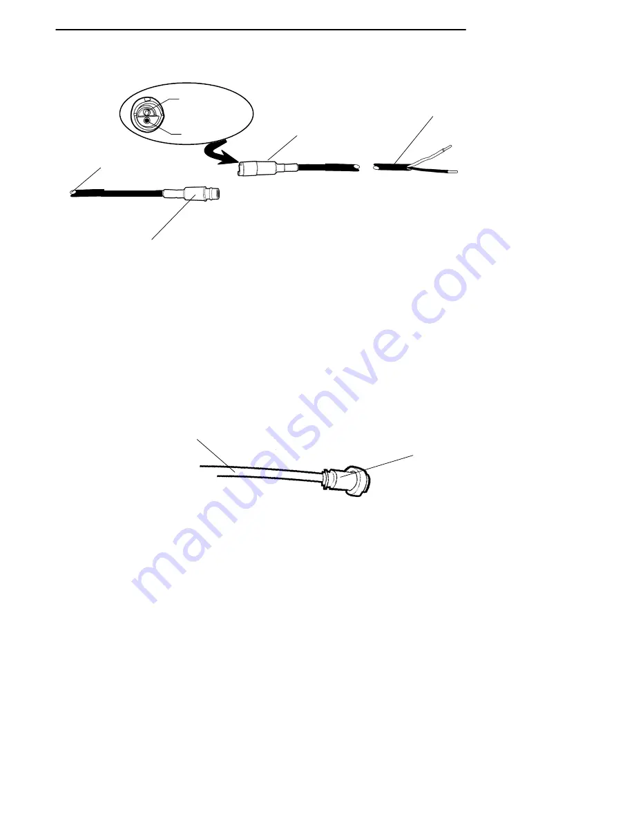
Figure 2-8

C

Co

on

nv

ve

errtte

err tto

o B

Ba

atttte

erry

y C

Ca

ab

blle

e

3

2

1. To vehicle battery, white wire-positive, black wire-negative
2. Rubber booted keyed connector
3. To dc-dc power converter

1

female connector

(positive)

male connector

(negative)

2

C

Co

on

nv

ve

errtte

err tto

o D

Do

occk

k C

Ca

ab

blle

e

The converter to dock cable is hardwired into the converter and has a
locking connector that is keyed to the dc power jack on the dock.

Figure 2-9

P

Po

ow

we

err C

Co

on

nv

ve

errtte

err tto

o D

Do

occk

k C

Ca

ab

blle

e

1. Keyed dock connector
2. From power converter

1

2

Summary of Contents for PEN*KEY 6400

Page 1: ...6400 Vehicle Dock INSTALLATION INSTRUCTIONS PN 962 020 006 Revision B August 1998...

Page 2: ...KEY are registered trademarks of Intermec Technologies Corporation 1997 Intermec Technologies Corporation All rights reserved This publication printed on recycled paper FCC Computer Compliance NOTICE...

Page 3: ...prise ait t sp cifiquement con ue pour tre utilis e dans les endroits humides Ne jamais toucher les fils de t l phone ou de l quipement terminal non isol s moins que la ligne t l phonique n ait t d b...

Page 4: ......

Page 5: ...ation Introduction 2 1 Installation Guidelines 2 2 Tools Required 2 3 Vehicle Installation 2 4 Installing the Cables 2 4 Routing the Cables 2 4 Power Cable Assembly 2 6 Assembling the In line Fuse Hol...

Page 6: ...e Ends 2 9 Figure 2 5 Side Mount Battery Terminals 2 11 Figure 2 6 Top Mount Battery Terminals 2 13 Figure 2 7 Vehicle Dock with Free Standing Mounting Plate 2 14 Figure 2 8 Converter to Battery Cable...

Page 7: ...elease the computer from the dock Bumper pads to protect and brace your computer when it is se cured in the dock The pad assembly can be rotated to accommo date your computer with an optional scanner...

Page 8: ...Instructions Figure 1 1 V Ve eh hi ic cl le e D Do oc ck k S Si id de e V Vi ie ew w 1 1 Pivoting computer bumper supports 2 Computer release levers 3 Rotating swivel base 4 Release lever for swivel...

Page 9: ...e er rt te er r The DC DC Power Converter is shown in Figure 1 2 The large mag nets on the bottom of the converter aid in mounting the unit Figure 1 2 D DC C D DC C P Po ow we er r C Co on nv ve er rt...

Page 10: ...on nn ne ec ct to or r Figure 1 3 V Ve eh hi ic cl le e D Do oc ck k 3 3 P Pi in n M Ma al le e P Po ow we er r C Co on nn ne ec ct to or r Pin 1 chassis ground green wire Pin 3 ground white wire Pin...

Page 11: ...echarge the batteries in your hand held computer NOTE Norand Corporation is not responsible for loss or damage to the hand held computers or docks resulting from improper installation NOTE Mounting br...

Page 12: ...Connect the power cable from the converter to the dock Connect the power cable to the vehicle battery terminals The dock mounting location must not restrict the drivers view Mount the dock and cables...

Page 13: ...ur equipment Defective ignition wiring damaged insulation or a faulty vehicle electrical component can cause electrical noise When this happens computers and other equipment can behave unpredictably T...

Page 14: ...es loose or sagging cables guarding against breakage and ensuring that they do not pose a hazard to the vehicle operator or to other workers R Ro ou ut ti in ng g t th he e C Ca ab bl le es s Decide t...

Page 15: ...pment 3 Cut the power cable near the battery to eliminate the need for coiling excess cable NOTE Do not cut the cable too short to reach the battery terminals 4 Strip the power cable jacket back 12 14...

Page 16: ...page 2 9 If the fuse holder is not preassembled carefully follow these instruc tions to assemble the in line fuse holder 1 Locate the in line fuse holder components 2 Cut the black wire in the power c...

Page 17: ...Dock Installation Instructions 2 2 7 7 Figure 2 2 A As ss se em mb bl li in ng g t th he e I In n l li in ne e F Fu us se e H Ho ol ld de er r 1 Fuse clips 2 Black wire 6 7 inches 3 Fuse holder boot...

Page 18: ...he black wire from the fuse holder See the battery drawing and instructions for recommended assembly to connect the cable to the vehicle battery 1 Strip approximately 1 4 of insulation from the white...

Page 19: ...cable when your kit includes a preassembled fuse holder 1 Strip the white wire 2 Crimp the 3 8 terminal ring 1 onto the white wire 3 Locate the fuse link 2 it attaches to the black wire 4 Shorten the...

Page 20: ...nished in kit 3 Slip a 3 8 inch washer 8 onto the battery terminal bolt 4 Slide the positive red wire fuse link 7 terminal ring from the battery cable onto the positive battery terminal bolt 5 Slip a...

Page 21: ...attery 2 Positive battery terminal 3 Battery cable positive 4 Fuse link 5 Black or brown wire negative 6 Power cable 7 Red wire positive 8 Washers 9 Battery terminal bolt positive 10 Nut 1 2 3 4 5 6 F...

Page 22: ...he bolts removed in step 1 with 3 8 x 1 1 2 bolts 4 and nut 10 furnished in the installation kit Tighten nut secure ly 3 Slip a 3 8 inch washer 9 onto the extended end of each battery terminal bolt 4...

Page 23: ...13 3 1 Battery 2 Positive battery terminal 3 Battery cable positive 4 3 8 x 1 1 2 bolt 5 Fuse link 6 Black or brown wire negative 7 Power cable 8 Red wire positive 9 Washers 10 Nut 2 9 1 3 4 5 6 Figur...

Page 24: ...n ng g M Mo ou un nt ti in ng g B Br ra ac ck ke et t K Ki it t 2 20 03 3 4 47 70 0 0 00 01 1 Description NPN Qty Free standing mounting plate 714 390 001 1 Phillips head screws 8 1 2 802 287 000 4 Fi...

Page 25: ...from the converter and three feet from the power source battery Any bends made during cable routing will further reduce the distance be tween vehicle batteries and the dock itself The converter shoul...

Page 26: ...ber booted keyed connector 3 To dc dc power converter 1 female connector positive male connector negative 2 C Co on nv ve er rt te er r t to o D Do oc ck k C Ca ab bl le e The converter to dock cable...

Page 27: ...nector to the key on the vehicle dock three pin connector 2 Slide the connector into the connector on the dock 3 Turn the nut on the cable connector clockwise to attach the cable to the dock Figure 2...

Page 28: ...ck The ve hicle dock can accept a held held computer with or without the optional scanner handle To review the key components of your vehicle dock refer to Figure 2 11 Figure 2 11 V Ve eh hi ic cl le...

Page 29: ...r insert a screwdriver into the slot in the screw head Figure 2 12 R Ro ot ta at ti in ng g t th he e B Bu um mp pe er r P Pa ad d Screw 2 Turn the key counterclockwise to unlock the keylock 3 Push th...

Page 30: ...ON N 2 2 Installation 2 2 2 20 0 6400 Vehicle Dock Installation Instructions Figure 2 13 I In ns se er rt ti in ng g t th he e C Co om mp pu ut te er r i in nt to o t th he e V Ve eh hi ic cl le e D...

Page 31: ...tion 6400 Vehicle Dock Installation Instructions 2 2 2 21 1 Figure 2 14 P Pu ut tt ti in ng g a a C Co om mp pu ut te er r w wi it th h S Sc ca an nn ne er r H Ha an nd dl le e i in n V Ve eh hi ic cl...

Page 32: ...nstructions J Ju um mp p S St ta ar rt ti in ng g Y Yo ou ur r V Ve eh hi ic cl le e B CAUTION If you need to jump start your vehicle from another vehicle battery disconnect the power cable running to...

Page 33: ...tion 2 10 top mount battery cable connec tion 2 12 Installation guidelines vehicle dock 2 2 Installing vehicle dock connecting the fuse holder 2 9 vehicle dock final cable connec tions 2 15 vehicle do...

Page 34: ...I IN ND DE EX X I In nd de ex x 2 2 6400 Docks Installation Instructions...

Reviews: