background image

Intermec EasyCoder PD4—Service Manual 

61

Chapter 10—Cutter

Clearing Media Jam in Cutter

To clear a media jam inside the cutter mechanism, follow the instructions 
below:

1

  At media jams and cutter malfunctions, switch off the power to the 

printer. 

Never insert fi ngers or tools into the printer while the power is still on. 
Risk of personal injury or damage to the cutter if the cutter starts to 
run by mistake.

2

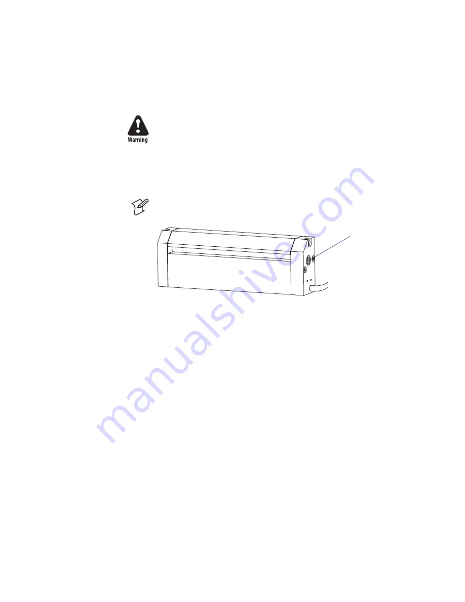
  Insert a 3 mm hexagon screwdriver in the hole on the side of the cutter 

(A) and turn the cutter blade clockwise. 

3

  After the media jam is cleared, switch on the power to the printer, and 

the cutter blade will go back to its original position. 

Note:

 It is recommended to use labels with a length of 35 mm (1.5 in) or 

more. 


A

Summary of Contents for EasyCoder PD4

Page 1: ...Service Manual EasyCoder PD4 Bar Code Label Printer ...

Page 2: ...ciTech CrossBar Data Collection Browser dcBrowser Duratherm EasyCoder EasyLAN Enterprise Wireless LAN EZBuilder Fingerprint i gistics INCA under license InterDriver Intermec Printer Network Manager IRL JANUS LabelShop Mobile Framework MobileLAN Nor Ware Pen Key Precision Print PrintSet Route Power TE 2000 Trakker Antares UAP Universal Access Point and Virtual Wedge are either trade marks or regist...

Page 3: ...tion against such inter ference when operated in a commercial environment Operation of this equipment in a residential area is likely to cause interference in which case the user at his own expense will be required to take whatever measures may be required to correct the interference EMS and EMI Compliance Statement This equipment has been tested and passed with the requirements relating to electr...

Page 4: ...iv Intermec EasyCoder PD4 Service Manual ...

Page 5: ...play 8 2 2 Front Panel with display 9 2 3 Replacing the Front Panel 10 2 4 Bottom Right Hand Panel 11 2 4 Console pcb 12 3 Side Panels 3 1 Right Hand Door 16 3 2 Left Hand Panel 17 4 Chassis 4 1 Chassis 20 4 2 Rear Plate 21 5 Media Supply 5 1 Media Supply Post 24 6 Transfer Ribbon Mechanism 6 1 Ribbon Module 28 6 2 Ribbon Module Belt 29 6 3 Ribbon Supply and Rewind Units 30 6 4 Ribbon Out Sensor 3...

Page 6: ...tions 70 12 4 Components 73 12 5 Test Points 74 12 6 Schematics 75 12 7 Memory Expansion Card 83 13 Interfaces 13 1 RS 232 Serial Interface 86 13 2 USB Serial Interface 87 13 3 Centronics Parallel Interface 88 14 Troubleshooting 14 1 Error Handling 90 14 2 Troubleshooting Check List 91 14 3 No Reaction at Power Up 93 14 4 Error During Printing 95 14 5 No Printing 96 14 6 Printing Partly Missing al...

Page 7: ...m stances Someone capable of providing first aid must always be present for your safety First aid Always obtain first aid or medical attention immediately after an injury Never neglect an injury no matter how slight it seems Resuscitation Begin resuscitation immediately if someone is injured and stops breath ing Any delay could result in death To work on or near high voltage you should be familiar...

Page 8: ...tion alerts you to an operating procedure practice condition or statement that must be strictly observed to prevent equipment damage or destruction or corruption or loss of data This icon appears at the beginning of any procedure in this manual that could cause you to touch components such as printed circuit boards that are susceptible to damage from electrostatic discharge ESD When you see this i...

Page 9: ...termec technical knowledge base Knowledge Central at http intermec custhelp com to review technical information or to request technical support for your Intermec product Telephone Support Contact your local Intermec representative To search for your local repre sentative from the Intermec web site click Contact Related Documents This table contains a list of related Intermec documents and their pa...

Page 10: ...termec Please note that the operations described in this manual only should be car ried out by skilled and authorized personnel with proper training and full understanding of written English The printers contain wires and circuits with high voltage which implies the risk of electrical shock Moving parts may also cause harm if incorrectly manipulated It is assumed that the reader possesses reasonab...

Page 11: ...Intermec EasyCoder PD4 Service Manual 1 1 Models and Options This chapter describes the various models of the EasyCoder PD4 printer family describes the option and provides technical specifications ...

Page 12: ... The EasyCoder PD4 comes in three main models Printer without display and 200 dpi printhead density Printer with display and 200 dpi printhead density Printer with display and 300 dpi printhead density EasyCoder PD4 without display 200 dpi EasyCoder PD4 with display 200 or 300 dpi ...

Page 13: ...s for the EasyCoder PD4 depend on the printer model External Keyboard Display Unit all models EasyLAN 10 External Ethernet Adapter all models Memory Expansion Board 2MB display models only Cutter display models only Rewinder display models only Keyboard Display Unit 2MB Memory Expansion Card ...

Page 14: ...4 Intermec EasyCoder PD4 Service Manual Chapter 1 Models and Options EasyCoder PD4 with cutter EasyCoder PD4 with rewinder right hand door not shown ...

Page 15: ...edia Roll Core Diameter 38 1 to 76 2 mm 1 5 to 3 in Media Thickness 60 µm to 250 µm 2 3 to 9 8 mils Transfer Ribbon Material Wax hybrid or resin Winding Ink on either inside or outside Ribbon Width 30 to 110 mm 1 18 to 4 33 in Ribbon Roll Diameter outer 76 mm 2 99 in Equivalent to 450 m 1 471 ft of ribbon at ribbon thickness 8 µm Inner Core Diameter 25 2 to 25 6 mm 1 00 inches Modes of Operation T...

Page 16: ...240 VAC 50 to 60 Hz Power Consumption approx Stand by 5W Peak 140W Sensors Label Gap Black Mark Out of Media Yes Moveable left aligned Printhead Lifted Yes Ribbon End Yes Label taken Yes1 Controls Control Lamps 3 Power Ready and Error Bi color Display Yes1 Graphic LCD with background light Control Keys 3 Feed Pause and Cancel Beeper Yes Data Interfaces Serial 1 x RS 232 1 x USB Parallel Yes Access...

Page 17: ...Intermec EasyCoder PD4 Service Manual 7 2 Front Panels This chapter describes the front panels for various models of the Easy Coder PD4 printer family ...

Page 18: ...which also contains the switches for the control keys and a buzzer An overlay provides the desig nations for the LEDs and keys The overlay is covered with a transparent plastic window The console pcb is connected to CN22 on the main board via a separate flat cable Refer to Chapter 2 3 for replacement instructions Flat cable Console pcb Dummy strip sensor E ring Screw and washer x4 Front panel moul...

Page 19: ...signations for the LEDs and keys The overlay is covered with a transparent plastic window The console pcb is connected to CN22 on the main board via a separate flat cable Refer to Chapter 2 3 for replacement instructions As opposed to the displayless model there is a working strip sensor that can detect whether labels have been removed from the outfeed slot or not The strip sensor is further descr...

Page 20: ...e flat cable from the main board 3 From inside the electronics compartment remove the two screws that hold the front panel assembly at the top front of the center section 4 Lift the front panel assembly up out so the panel moulding disengages the two keyholes in the center section 5 In case of a EasyCoder PD4 with display disconnect the strip module cable from CN12 on the main board and remove it ...

Page 21: ...bottom plate in front of the print mechanism This panel is temporarily removed when loading media for peel off self strip operation in connection with an optional rewinder see Chapter 8 It must be permanently removed before installing an optional cutter see Chapter 10 The panel is held by a knurled screw inserted from beneath the bottom plate ...

Page 22: ... R8 Q3 Q4 Q2 Q1 CN1 CN2 5V U1 U3 A K U2 C17 C18 5V C19 R39 D4 C4 R14 R13 R23 R7 R25 BZ1 C3 R12 R15 R38 R41 R40 R37 C2 C1 VR1 VR2 C8 C9 C10 C11 C12 C13 C14 C5 C15 200 000103 02 HC14 LS32 LS08 12 Intermec EasyCoder PD4 Service Manual Chapter 2 Front Panels 2 5 Console pcb Components ...

Page 23: ...R 8 R 4 C 1 R V 1 R 5 2 R 9 R 8 1 R 1 2 3 4 5 6 7 8 1 1 R B 3 U 4 5 6 C 1 U 9 0 1 8 A 3 U 1 2 3 4 N C 1 2 3 4 5 6 7 8 9 10 11 12 13 14 9 N C 1 2 3 4 5 6 7 8 9 0 1 1 1 2 1 3 1 4 1 5 1 6 1 7 1 8 1 9 1 0 2 5 1 C 5 3 R 2 R 1 Z B 2 1 4 1 C 7 R 3 1 C 5 1 R 2 2 R 3 N C 1 2 3 4 5 6 7 8 9 0 1 1 1 2 1 3 1 4 1 5 1 6 1 2 1 C 0 2 R B 2 U 3 4 1 1 C 5 C E 2 U 1 1 0 1 0 1 C 7 1 R 1 2 3 4 5 6 7 8 1 Q 4 2 R 9 C 6 1...

Page 24: ...14 Intermec EasyCoder PD4 Service Manual Chapter 2 Front Panels ...

Page 25: ...rmec EasyCoder PD4 Service Manual 15 3 Side Panels This chapter describes the right hand door assembly that covers the media compartment and the left hand side panel that covers the electronics com partment ...

Page 26: ... load The door assembly consists of a hinged door to which the top right panel is fitted using four screws A clear plastic inspection window is glued the inside of the door A media and ribbon load instructions label is fitted inside the top part of the door Replacement The door assembly is available as a complete unit The hinges are attached to the center section using a total of 4 screws not incl...

Page 27: ... Description The left hand panel covers the electronics compartment It is a one piece metal panel which is fitted to the center section using two screws and to the rear plate and the bottom plate using series of leaf springs along the edges Panel Screw Screw Leaf springs Leaf springs ...

Page 28: ...nics com partment 1 Disconnect the power cord 2 Open the right hand door 3 Remove the screws in front of the front hinge and to the rear of the rear hinge 4 Close the right hand door 5 Using for example a flat tipped screwdriver pry the panel upwards until it comes free Protect the paint by inserting for example a thin piece of cardboard or similar between the plate and the screwdriver 6 Put the p...

Page 29: ...Intermec EasyCoder PD4 Service Manual 19 4 Chassis This chapter describes chassis which consists of the center section the bottom plate and the rear plate ...

Page 30: ...hanism the transfer ribbon mechanism the electronics and the media supply post It consists of three main parts Bottom plate with four rubber feet and two dampeners for the right hand door Center section two different the displayless model has no hole for the rewinder and no cover plate Rear plate Bottom plate Rubber feet x4 Rewinder cover plate display model only Dampeners x2 Rear plate Center sec...

Page 31: ...tains the On Off switch and AC power cord socket assembly and the serial port connector It also has slots for the parallel interface connector and the USB connector which are fitted on the main board Serial port Parallel port USB port AC power cord socket On Off switch Slot for external media supply Label ...

Page 32: ...Serial port connector cable not shown Power switch kit cables not shown 22 Intermec EasyCoder PD4 Service Manual Chapter 4 Chassis ...

Page 33: ...Intermec EasyCoder PD4 Service Manual 23 5 Media Supply This chapter describes the media supply post with its two types of edge guide ...

Page 34: ...acked separately The short guide makes it easy to fit the media roll but does not support the entire side of the roll The tall edge guide supports most of a full media roll but must be folded to a horizontal position to allow a roll or empty core to be remove and a new roll to be loaded Which guide to use depends mainly on the characteristics of the media in use for example a slippery liner versus...

Page 35: ...washer and then the coil spring from underneath the post to the protruding part of the edge guide and engage the coil spring to the hook Note The high edge guide is hinged to allow media load Before remov ing an empty core or loading a roll of media the guide must be flipped down to a horizontal attitude Likewise after loading the media it must be flipped back so it points straight up Like the low...

Page 36: ...26 Intermec EasyCoder PD4 Service Manual Chapter 5 Media Supply ...

Page 37: ...Intermec EasyCoder PD4 Service Manual 27 6 Transfer Ribbon Mechanism This chapter describes the thermal transfer ribbon mechanism ...

Page 38: ...ribbon out sensor and the ink position knob are also replaceable To replace the entire ribbon module follow these instructions 1 Disconnect the power cord and remove the left hand panel as described in Chapter 3 2 Carefully read the safety instructions in Chapter 3 2 2 Slip the belt that drives the platen from its pulley also see Chapter 7 2 3 Use a pair of narrow pliers to disconnect the spring b...

Page 39: ...he washer from the ends of the ribbon supply and rewind shafts 4 Remove the four screws that hold the inner bracket to the main body of the ribbon module and pull out the bracket DO NOT loosen the screws that hold the bearing and the one way clutch to the bracket That will affect the factory adjustment of the supply and rewind units and can cause ribbon creasing problems 5 Remove the belt from the...

Page 40: ...a single screw Ribbon Tension Adjustment The knob at the outer end of each unit is engraved with numbers from 1 to 4 where 1 is maximum friction and 4 is less friction Factory default is 1 on the supply unit and 2 on rewind unit If the friction settings prevent the ribbon from running with the same speed as the media smudging may occur If ribbon wrinkling occurs during printing push the knob on th...

Page 41: ...p for direct thermal printing the ribbon out sensor is not used Replacement Before replacing the sensor check that the malfunction is not caused by dust or foreign objects Also disconnect and connect the cable to the main board a few times to remove any oxide To remove the ribbon out sensor follow these steps 1 Disconnect the power cord and remove the left hand panel as described in Chapter 3 2 Ca...

Page 42: ...onnect the power cord and remove the left hand panel as described in Chapter 3 2 Carefully read the safety instructions in Chapter 3 2 2 Disconnect the spring from the ink position knob inside the electronics compartment using tweezers or a pair of narrow tipped pliers 3 Move the knob to the center of the slot rotate it a quarter of a turn and pull it out into the media compartment 4 Install the i...

Page 43: ...Intermec EasyCoder PD4 Service Manual 33 7 Print Mechanism This chapter describes the print mechanism and the stepper motor that drives both the platen roller and the transfer ribbon takeup unit ...

Page 44: ...ead The main board the printhead connector the platen roll pulley and the platen roll belt must also be replaced which makes such an operation uneconomi cal Never use non approved printheads The main board will probably get damaged beyond repair and the warranty will be void To help understanding the design of the print unit an exploded view of all parts except cables are shown below Replacement p...

Page 45: ...y the double pulley motor is available as a spare part but can also be used in the displayless model even if the outer part of the pulley is not used There are two different belts one for 203 2 dpi printheads and one for 300 dpi printheads Likewise there are two different pulleys on the platen roller shaft The tension of the belt is automatically adjusted by a springloaded arm and wheel arrangemen...

Page 46: ...cable from the spiral bindings and the cable clip 3 Remove the four screws that hold the stepper motor module to the bottom plate 4 Disconnect the belt s from the motor s pulley and pull out the motor 5 Install belt and motor in reverse order Make sure the belt is intended for the type of printhead 203 2 or 300 dpi installed in the printer In case of a printer prepared for a rewinder fit the plate...

Page 47: ... stepper motor may generate current that can damage the electronics You could also disconnect the stepper motor cable from the main board Replacement To remove the platen follow these steps 1 Disconnect the power cord and remove the left hand panel as described in Chapter 3 2 Carefully read the safety instructions in Chapter 3 2 2 Remove the front panel as described in Chapter 2 3 this step can be...

Page 48: ...tted flush to the inner gable of the print module whereas the outer one should be adjusted to fit the width of the media without compressing it It can be folded upward to facilitate media load Replacement The media guides are pressed onto their respective shafts and can easily be removed and installed by hand Take care to fit the guides as illustrated below that is the flat side should face the me...

Page 49: ...rmine the position of the labels or similar along the media path and also detect out of media conditions Adjustments Lateral Position The label gap sensor s point of detection can be moved manually across the media path from 0 to 57 mm 0 to 2 24 in from the inner edge of the media The point of detection is indicated by a narrow white triangle vis ible from the front of the print mechanism when the...

Page 50: ...g from the outer end of the platen roller that is the end in the media compartment 3 Remove six screws that hold the outer gable of the printhead 4 Fold the outer gable aside taking care not to damage the headlift sensor and its cable see Chapter 7 6 5 Remove the single screw that holds the label gap sensor module in the electronics compartment It is situated immediately to the rear of the black s...

Page 51: ...ensor follow these steps 1 Disconnect the power cord and remove the left hand panel as described in Chapter 3 2 Carefully read the safety instructions in Chapter 3 2 Open the right hand door and remove the bottom right hand panel see Chapter 2 4 2 Disconnect the cable from CN14 DOOR on the main board Free the cable from the spiral binding and the cable clips 3 Remove the E ring washer and bearing ...

Page 52: ...i ately becomes solid again producing a black spot Transfer ribbons nor mally do not smear at room temperature neither before nor after printing Nor do the printed labels smear even if the printout may be smudged by extensive rubbing if an unfortunate combination of ribbon and face mate rial is used The thermal transfer method makes it possible to use a wide range of face materials for printing fo...

Page 53: ...to the right for wider media and inwards to the left for more narrow media 5 Engage the printhead and load the ribbon 6 Test and readjust if necessary Hint If you use direct thermal media you will not have to load and remove the ribbon over and over again Printhead Pressure The pressure of the thermal printhead against the platen roller is factory adjusted However if the printing is weaker on one ...

Page 54: ...essary Hint If you use direct thermal media you will not have to load and remove the ribbon over and over again Printhead Dot Line Position When using thick or stiff media the printhead needs to be moved forward so the dot line becomes exactly aligned with the top of the platen roller Obviously the platen roller and printhead must also be completely in parallel To perform this adjustment follow al...

Page 55: ...08 in Make sure to make identical adjustments on both the screws If you get lost tighten both screws by turning them counterclockwise as far as they go and start all over again 6 Important step Engage the printhead and lock the printhead by tight ening the two screws at the top of the printhead bracket that is the reverse action of step 3 7 Load the ribbon only in case of thermal transfer printing...

Page 56: ... off The firmware will not detect the new printhead resistance until the printer has been restarted Take precautions against electrostatic discharges by touching a grounded object for example the chassis of the printer assuming the printer is connected to a grounded wall socket Install a replacement printhead this way 1 Switch off the power to the printer 2 Open the side door 3 Lift the printhead ...

Page 57: ...igher printhead pressure than necessary Never print outside the media path Dots that are not in contact with the media will not be cooled properly When using media with less than full width be careful to adjust the printhead balance so there is an even pressure across the media Not only will an uneven pressure impair the printout quality but it may also pre vent the dots from being properly cooled...

Page 58: ...48 Intermec EasyCoder PD4 Service Manual Chapter 7 Print Mechanism ...

Page 59: ...r PD4 Service Manual 49 8 Rewinder Module This chapter describes the optional internal liner rewinder required for peel off self strip operation The rewinder can only be fitted on Easy Coder PD4 printers with a display ...

Page 60: ...They are also prepared with wiring and a connector for the rewinder module s takeup full sensor A removable plate covers the hole in the center section for the rewinder The rewinder module consists of the following parts Only the liner reten tion clip and the liner takeup full sensor are available as spare parts The cable from the takeup full sensor is not shown in this drawing Cover plate Cutter ...

Page 61: ...rator following these steps 1 Remove the screw that holds the front cover Remove the front cover 2 Open the side door and remove the rewinder option cover plate which is held by two screws 3 Remove the U shaped clip and attach the rewinder unit to the center section using the four screws included in the kit Cover plate Front cover Screw ...

Page 62: ...ce Manual Chapter 8 Rewinder Module 4 Plug in the cable from the rewinder switch into the front one of the two connectors in the center section 5 Install the media as described in the EasyCoder PD4 User s Guide Rewinder cable Switch ...

Page 63: ... Service Manual 53 9 Strip Module This chapter describes the strip module also called label taken sensor which is a standard feature on EasyCoder PD4 printers with a display It cannot be fitted on printers without a display ...

Page 64: ...ide of the front panel see Chapter 2 2 but can be folded down to a horizontal position after the right hand door has been opened In the horizontal position it detects labels approximately 15 mm 0 59 in from the inner edge of the media path and approximately 22 mm 0 86 in in front of the printhead s dot line The strip module can not be used when a paper cutter is installed The strip module consists...

Page 65: ...Chapter 3 2 The electronics compartment contains high voltages wires and circuitry Disconnect the power cord to eliminate the risk of electric shock and short circuits Take standard precautions against ESD Electrostatic Discharges before touching any electronics components 2 Disconnect the flat cable from the main board 3 Remove the front panel module as described in Chapter 2 3 4 Disconnect the s...

Page 66: ...56 Intermec EasyCoder PD4 Service Manual Chapter 9 Strip Module ...

Page 67: ...syCoder PD4 printers with a display It cannot be fitted on printers without a display Never use the cutter to cut through any kind of adhesive which will get stuck on the shears and render the cutter inoperable or even damage it If you need to cut self adhesive labels be careful to cut the liner between labels ...

Page 68: ...t non adhesive media 64 to 118 mm 2 52 to 4 65 in wide and with a thickness of 60 to 250 µm 2 3 to 9 8 mils The cutter comes in three main parts Cutter mechanism including cable Cutter front panel Tray Control The cutter is controlled in the Setup Mode see the EasyCoder PD4 User s Guide or using an O command see ESim v5 xx for EasyCoder PD4 Pro grammer s Reference Manual Replacement Parts In addit...

Page 69: ...the screw that holds the front cover Remove the front cover 2 Open the side door and remove the tear bar which is held by two Phil lips screws 3 Attach the cutter mechanism to the printer using the two Phillips screws and washers included in the kit Tear bar Screws Front cover Screw ...

Page 70: ... connectors in the center section and fasten the cable to the bottom plate using the two cable clips included in the kit 5 Attach the cutter cover onto the cutter mechanism by first connecting the hooks on the back side of the cover over the cutter mechanism and then locking the cover with the screw at the bottom 6 If needed fit the tray to the front of the cutter ...

Page 71: ...gers or tools into the printer while the power is still on Risk of personal injury or damage to the cutter if the cutter starts to run by mistake 2 Insert a 3 mm hexagon screwdriver in the hole on the side of the cutter A and turn the cutter blade clockwise 3 After the media jam is cleared switch on the power to the printer and the cutter blade will go back to its original position Note It is reco...

Page 72: ...62 Intermec EasyCoder PD4 Service Manual Chapter 10 Cutter ...

Page 73: ...Intermec EasyCoder PD4 Service Manual 63 11 Switching Power Module This chapter describes the switching power module and its connections from the power switch unit and to the main board ...

Page 74: ...tand by 0 15A Normal operation 4 5A Peak 10 5A Switched power modules are generally difficult to repair If one compo nent fails due to aging or overload a number of other components will also break as a consequence They are hard to troubleshoot because the power module often is dead or the fuses blow immediately It is also impossible to guarantee the life of a repaired power module because compone...

Page 75: ...er cord to eliminate the risk of electric shock and short circuits Take standard precautions against ESD Electrostatic Discharges before touching any electronics components 2 Disconnect the two cable harnesses at the rear of the power module 3 Remove the two screws at the front of the power module that hold it to the bottom plate 4 Push the module forward so as to disengage the tab at the rear and...

Page 76: ... C17 LF1 4 2 3 1 R9 R10 R11 ZD2 ZD1 JP1 C7 C9 D1 D4 D2 BO1 Q1 HS1 AUTEC UPS 110 1001 REV B R11 VR1 R10 C8 R9 3 1 2 7 6 5 4 R5 R7 Q1 HS1 D3 HS2 R8 L1 D2 D1 C6 C2 BD1 CN1 F1 L N FC CONT1 C1 R1 VDR1 TR1 LF1 C3 C4 C5 HV HV C9 C10 C11 C17 C12 C13 L2 C14 R14 R18 R19 R16 ZD1 CN3 LED 24V GND CN2 SCR1 R3 R12 HV R6 R4 R2 24V 66 Intermec EasyCoder PD4 Service Manual Chapter 11 Switching Power Module Componen...

Page 77: ...Intermec EasyCoder PD4 Service Manual 67 12 Main Board This chapter describes the three different main boards including connec tions test points component placement and schematics ...

Page 78: ...r the EasyCoder PD4 depending on printer model EasyCoder PD4 No display 203 2 dpi EasyCoder PD4 LCD display 203 2 dpi EasyCoder PD4 LCD display 300 dpi The printer must be fitted with the correct type of main board or it will not work All types of main board are based on the same circuit board but the com plement of circuits differ They are all designed to work with ESim v5 xx for EasyCoder PD4 or...

Page 79: ...ock and short circuits Take standard precautions against ESD Electrostatic Discharges before touching any electronics components 2 Disconnect all cables from the main board It may be a good idea to mark them up first 3 In case there is a memory expansion board installed remove it see Chapter 12 7 4 Remove the five screws and washers that hold the main board In case of a memory expansion board ther...

Page 80: ... Service Manual Chapter 12 Main Board 12 3 Connections EasyCoder PD4 no display 203 2 dpi CN11 Ribbon out CN23 RS 232 CN14 Headlift CN8 Black mark CN9 See through JP4 USB CN21 Centronics CN7 Motor CN28 Power CNA1 CNB1 Printhead ...

Page 81: ... EasyCoder PD4 display 203 2 dpi CN11 Ribbon out CN23 RS 232 CN12 Strip module CN17 Rewinder full CN14 Headlift CN8 Black mark CN9 See through CN22 LCD Panel JP4 USB CN21 Centronics CN19 Cutter CN7 Motor CN28 Power CNA1 CNB1 Printhead CN3 CN4 Memory expansion card ...

Page 82: ...oard EasyCoder PD4 display 300 dpi CN11 Ribbon out CN23 RS 232 CN12 Strip module CN17 Rewinder full CN14 Headlift CN8 Black mark CN9 See through CN22 LCD Panel JP4 USB CN21 Centronics CN19 Cutter CN7 Motor CN28 Power CN5 Printhead CN3 CN4 Memory expansion card ...

Page 83: ...54 C48 C14 C19 C18 R61 R59 C52 C49 C13 C55 R73 R72 C51 R68 R65 C59 C112 R84 R52 R78 R50 R58 R148 SEE R147 BLACK R56 R57 R51 C44 R62 R60 STRIP DOOR COVER REWINDFUL R69 R67 RIBBONOUT RIBBONEND SPSTMP R2 R1 C140 R153 R162 R150 Q4 R5 R10 JP1 C141 C131 C132 R6 R7 U2 U7 U3 U6 C128 U11 U10 R8 C5 CN10 CN11 CN13 CN12 C17 C16 C109 CN14 CN20 R180 CN8 CN9 CN22 R53 Q1 U9 U8 C111 C67 C117 C143 L10 C46 R181 CN17...

Page 84: ...LPT port busy USBFXF U40 Pin 12 USB data in interrupt PDAT CN5 Pin 19 Printhead serial data PCLK CN5 Pin 15 Prithead serial clock PHLTH CN5 Pin 20 Printhead data latch HCTL U15 Pin 9 Printhead control STB1 U18 Pin 10 Printhead strobe BLACK U28 Pin 2 Black mark sensor SEE U28 Pin 24 See_through sensor THPM CN5 Pin 9 Printhead temperature sensor STRIP CN9 Pin 2 Strip sensor POT_CS U28 Pin 11 Potenti...

Page 85: ...NC I O8 I O9 I O11 Vss I O10 I O12 I O13 I O15 Vss I O14 WE 3 C 1 L 1 2 3 R 0 1 C 9 C 8 R 4 1 C 1 C 9 3 1 R 7 C 8 C 2 U 1 2 3 4 5 6 7 8 9 0 1 1 1 2 1 3 1 4 1 5 1 6 1 7 1 8 1 9 1 0 2 1 2 2 2 3 2 4 2 41 42 43 44 45 46 47 48 49 50 51 52 53 54 55 56 57 58 59 60 61 62 63 64 65 66 67 68 69 70 71 72 3 7 4 7 5 7 6 7 7 7 8 7 9 7 0 8 40 39 38 37 6 3 5 3 4 3 3 3 2 3 1 3 0 3 9 2 8 2 7 2 6 2 5 2 1 8 2 8 3 8 4 ...

Page 86: ... B N I B N I A T U O A T U O B T U O B T U O A S V B S V A D T B D T A S R A F E R B F E R B S R A G B G 6 3 R 8 3 C 7 N C 1 2 3 4 9 4 R P 9 3 R 2 D 1 2 3 3 C 6 N C 1 2 3 4 5 6 9 3 C 2 3 C 7 3 C 0 4 C 7 3 R 1 3 C 3 D 1 2 3 3 R 0 2 U 1 2 3 4 5 6 7 8 9 0 1 1 1 2 1 3 1 4 1 5 1 6 1 B M T M M V D N G D N G C C V 1 I 0 I E S A H P C R V D N G D N G M M V A M E V 0 5 F p 0 2 8 V 5 3 F u 7 4 P I D K 1 0 7...

Page 87: ... L C Q Q 5 7 1 R 1 D 7 Q 1 A N C 1 2 3 4 5 6 7 8 9 0 1 1 1 2 1 3 1 4 1 5 1 1 B N C 1 2 3 4 5 6 7 8 9 0 1 1 1 2 1 3 1 4 1 5 1 B 8 1 U 4 5 6 D 8 1 U 2 1 3 1 1 1 A 7 1 U 9 3 3 M L 7 6 1 3 12 1 3 R B 7 1 U 9 3 3 M L 5 4 2 3 12 A 8 1 U 1 2 3 3 6 1 R C 7 1 U 9 8 4 1 3 12 4 2 C B 4 U 3 4 8 2 C 6 7 1 R D 6 1 U 2 1 3 1 1 1 7 1 R K 0 1 6 2 C 8 1 R K 0 1 3 2 R K 0 1 5 2 C 9 2 R C 4 U 5 6 0 2 R 6 2 R K 0 1 C ...

Page 88: ... V S I C D 6 2 1 R 6 3 1 R 1 D Z 4 3 1 R 1 X F 1 2 4 3 0 2 1 C 4 L 9 1 1 C 1 2 1 C 8 L 1 2 7 1 1 C 8 1 1 C 2 1 L 1 2 5 2 1 C 6 2 1 C 2 3 1 R 5 L 0 1 L 1 2 3 2 1 C 8 2 1 R 2 2 1 C 9 2 N C 2 3 1 7 2 1 R 7 2 N C 1 2 3 4 4 2 1 C 9 2 1 R 5 3 1 R D 7 1 U 1 1 0 1 3 1 3 12 1 3 1 R 8 2 N C 1 2 3 4 5 6 7 D 7 L A 5 E S U F 78 Intermec EasyCoder PD4 Service Manual Chapter 12 Main Board Power ...

Page 89: ... B 2 A 2 W 4 D N G A 4 B 4 A 4 W D N G D N D H S S C O D S I D S K L C S R D D V 3 D N G A 3 W 3 A 3 B 1 D N G A 1 W 1 A 1 B 9 1 N C 5 R E D A E H CUTTER 1 2 3 4 5 9 D 6 4 C 1 8 1 R K 5 R 1 1 D 1 6 R 4 6 R 3 8 R 1 5 C 3 5 C 2 6 1 R 9 5 R 9 N C E E S 1 2 3 5 5 R K C A L B 8 N C 1 2 3 4 4 5 R 8 5 C 5 P J 3 5 R 2 5 C 9 6 R 1 8 R 2 6 R 2 Q 6 5 R 3 7 R 4 Q 1 5 1 R 7 1 N C L U F D N I W E R 1 2 0 5 1 R ...

Page 90: ... 1 4 3 6 5 8 7 0 1 9 2 1 1 1 4 1 3 1 6 1 5 1 8 1 7 1 0 2 9 1 2 2 1 2 4 2 3 2 6 2 5 2 6 3 1 C 4 1 1 C 2 8 C 5 1 1 C 1 8 C C 4 2 U 9 0 1 8 9 7 C 7 2 U 1 3 4 5 4 1 7 3 1 8 6 1 2 5 1 6 1 1 0 1 2 1 9 1 3 4 5 T O 1 T T O 2 T N I 1 R N I 2 R 6 1 2 5 1 6 N I 1 T N I 2 T T O 1 R T O 2 R 4 T R 3 T R 3 9 C 4 2 N C 1 2 3 4 5 6 7 8 9 0 1 1 1 2 1 3 2 N C 1 2 3 4 5 6 7 8 9 0 1 5 2 U 1 2 3 4 5 6 7 8 9 0 1 1 1 2 1...

Page 91: ... R 3 8 C 0 2 D 0 0 1 R 2 7 C 3 2 D 3 0 1 R 9 3 U 1 2 4 6 8 9 1 1 1 3 1 5 1 7 1 8 1 6 1 4 1 2 1 9 7 5 3 G 1 1 A 1 2 A 1 3 A 1 4 A 1 G 2 1 A 2 2 A 2 3 A 2 4 A 2 1 Y 1 2 Y 1 3 Y 1 4 Y 1 1 Y 2 2 Y 2 3 Y 2 4 Y 2 4 0 1 R 5 7 C 4 9 R 8 8 R 2 6 C 2 0 1 R 3 6 C 6 6 C 5 2 D 4 6 C 5 6 C 7 2 D 1 7 C 8 7 C 8 2 D 5 0 1 R 6 2 U 3 2 4 5 7 6 8 9 3 1 2 1 4 1 5 1 7 1 6 1 8 1 9 1 1 1 1 0 Q 0 D 1 Q 1 D 2 Q 2 D 3 Q 3 D...

Page 92: ...R 6 6 1 R 7 6 1 R 1 7 1 R 9 6 1 R 5 Q 0 7 1 R A 4 2 U 1 2 3 2 7 1 R 3 8 1 R 4 6 1 R 0 4 U 5 2 4 2 3 2 2 2 1 2 0 2 9 1 7 8 6 7 2 8 2 1 3 4 2 3 1 2 3 29 9 8 1 13 17 5 4 1 5 1 6 1 2 1 0 1 30 26 1 1 0 D 1 D 2 D 3 D 4 D 5 D 6 D P D B S U M D B S U T U O 3 V 3 N I T X T U O T X K L C C R T E S E R S C E E K S E E A T A D E E VCC AGND GND 7 D VCC GND T S E T E X T R W D R F X R T N G E E AVCC VCC Q E R E...

Page 93: ...rd precautions against ESD Electrostatic Discharges before touching any electronics components 2 Remove the screw and washer at the center of the main board and replace it with the hexagonal spacer delivered with the expansion card 3 Connect the expansion card to CN3 and CN4 on the main board making sure that the hole at the center of the card corresponds to the threaded hole in the spacer If the ...

Page 94: ...84 Intermec EasyCoder PD4 Service Manual Chapter 12 Main Board ...

Page 95: ...Intermec EasyCoder PD4 Service Manual 85 13 Interfaces This chapter describes the communication interfaces of the EasyCoder PD4 RS 232 serial interface USB serial interface Centronics parallel interface ...

Page 96: ...r PD4 v5 xx Programmer s Reference Manual as follows Baud rate 4 800 bps 9 600 bps 19 200 bps 38 400 bps Parity No parity Odd parity Even parity Data length 7 bits 8 bits Stop bit s 1 bit 2 bits Handshaking is XON XOFF and RTS CTS One line contains 5 VDC max 500mA permanently enabled The connector on the printer s rear plate is a DB 9pin socket Signals Pin Signal Meaning Remark 1 External 5 VDC Ma...

Page 97: ...your PC The printer is a so called self powered device You can connect the printer to a USB port on the host either directly or via a hub Keyboards mouses or more printers can also be connected to the same hub Using a USB Class A B cable connect the Class A plug to your PC or hub and the Class B plug to your printer There is no communication setup for the USB port USB Class A connector Connect to ...

Page 98: ...nter BUSY connects to the host Interface cable Parallel cable compatible to IBM PC One line contains 5 VDC max 500 mA permanently enabled Pinout Description Pin Function Transmitter Comment 1 Strobe host 2 9 Data 0 7 host 10 Acknowledge printer 11 Busy printer 12 Paper empty printer 13 Select printer 14 16 Not connected 17 Chassis ground 18 External 5 VDC Max 500mA permanently enabled 19 30 Signal...

Page 99: ...14 Troubleshooting This chapter describes how to troubleshoot the EasyCoder PD4 printer and suggests remedies which in most cases means identifying a faulty part and replacing it Do not attempt repairing the power supply or any circuit boards ...

Page 100: ...he Feed key 04 Insufficient memory to store data Press the Feed key 05 Memory configuration error Press the Feed key 07 Out of media Load new supply of media 08 Form or image name duplicate Press the Feed key 09 Form or image not found Press the Feed key 11 Print head lifted Close the printhead 13 Label taken sensor waiting Remove label 15 Rewinder is full Remove wound up liner 16 No form was retr...

Page 101: ... correct media and print type Chapter 14 5 Check that the printhead is properly connected to the print mechanism Chapter 14 5 Check that the printhead cables are properly connected to the main board Chapter 14 5 Check the main board Chapter 14 5 When printing label is jammed or tangled up Clear the media jam and if label is stuck on thermal printhead remove it using a soft cloth soaked with iso pr...

Page 102: ...across media path Check printhead balance Chapter 7 7 When using cutter label was not cut straight Check if media is loaded correctly User s Guide When using cutter label was not cut successfully Check if media is loaded correctly User s Guide Check that media thickness does not exceed 250 µm 9 8 mils When using cutter label could not feed or abnormal cutting occurs Check if cutter is installed pr...

Page 103: ...again Power switch or cables to power module defect Using a voltage meter check voltage between black and white wire in the connector at the power module end of the cable harness Defect power module Check fuse F1 on power module If blown replace only once with a 5A slow fuse If it blows again replace the entire power module Check 24 VDC output on CN2 on the power module between line and ground the...

Page 104: ...er 11 1 Cable between main board and console board not connected or dam aged Check that the cable is properly connected to CN22 on the main board and CN1 on the console board and that there is no visible damage Replace if necessary Faulty console unit Try connecting the cable to a replacement console board without actually installing it mind the risk of electrostatic discharges If the trouble seem...

Page 105: ...r is locked If the printhead actually is closed and locked but error 11 is still reported the headlift sensor may be out of order Check connection to CN14 on the main board Check headlift microswitch see Chap ter 7 6 and replace if necessary Check for jammed or entangled media or ribbon If found clear and reload Clean parts that may have been exposed to the media s adhesive using isopropyl alcohol...

Page 106: ...e Setup mode or program commands depending on whether the printer has a display or not see User s Guide Bad connection between printhead and main board Check that the printhead is properly inserted into the print mecha nism see Chapter 7 7 Check that the cables running from the print mechanism to the main board are not visibly damaged and that they are properly connected to the main board see Chap...

Page 107: ...k the printhead for dirt adhesive residue contamination from the back side of the transfer ribbon stuck labels etc If necessary clean as described in the User s Guide using isopropyl alcohol or a cleaning card Never use any sharp tools As a last resort replace the printhead see Chapter 7 7 Printhead damaged One or more of the heat sensitive resistors dots on the printhead has been damaged or is wo...

Page 108: ...rly connected to CN8 and CN9 on the main board Check that the printer is set the proper paper type Black mark Gap paper Plain paper With the power on check signals on U28 pin 2 Black Mark and U28 pin 24 See Through on the main board while manually pulling a media with gaps or black marks through the two parts of the sensor If no reaction the sensor needs replacing as described in Chapter 7 5 The m...

Page 109: ...der if the black marks have sufficient blackness or if there is some kind of printing on the back of the media that may interfere with the label gap sensor Bad friction between platen roller and media Check if the platen roller is slippery worn out or dry and hard Clean or replace if necessary see Chapter 7 3 ...

Page 110: ...100 Intermec EasyCoder PD4 Service Manual Chapter 14 Troubleshooting ...

Page 111: ...Intermec EasyCoder PD4 Service Manual 101 A Firmware Upgrading This appendix describes how to upgrade the printer with a new firmware version ...

Page 112: ...nglish An upgrading file ufz The Intermec EasyCoder PD4 Config Tool comes with a collection of firmware upgrading files New files can be downloaded from the Intermec Web site http www intermec com and should be located in the subfolder Firmware A host computer running Microsoft Windows with a parallel USB or RS 232 connection to the EasyCoder PD4 Parallel or USB connec tions are recommended Instru...

Page 113: ......

Page 114: ...ec Technologies Corporation Corporate Headquarters 6001 36th Avenue West Everett WA 98203 U S A tel 425 348 2600 fax 425 355 9551 www intermec com 1 960618 00 Intermec EasyCoder PD4 Service Manual 1 960618 00 ...

Reviews: