Chapter 2 — Installation Process
20
Vehicle Power Supply Installation Guide
Heat Shrink Tubing
This kit contains a 6 inch (15 cm) length of 3/8-inch heat shrink
tubing which you will cut into three pieces, and a 12 inch (30
cm) length of 1/8-inch heat shrink tubing for the shield wire.
To install heat shrink tubing
1
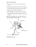
Crimp terminal rings and fuse holder ends, then position all
heat shrink tubing in the locations shown in the illustration
that follows.
2
Use a heat gun to shrink tubing.
3
Use the 1/8-inch shrink sleeve tubing over shield wire to
prevent contact with other live (powered) circuits.
Note
: Make sure that the negative input connector
wires connect to pins 1 and 2 of the input connector.
Check that the other two wires connect to pins 3 and
4 of the input connector. Be sure to separate and pull
out the shield wire.
Note:
Tubing must be in place before terminating
wire ends.
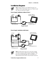
Green and white wires (negative)
Red and black wires (positive)
Shield wire with heat shrink applied
Strip the cable jacket 12-14 inches (30-36 cm)
Input power cable
Heat shrink tubing
see note below
see note below
Summary of Contents for CV60
Page 1: ...Vehicle Power Supply Installation Guide ...
Page 4: ...iv Vehicle Power Supply Installation Guide ...
Page 10: ...Vehicle Power Supply Installation Guide x ...
Page 20: ...Chapter 1 Introduction 10 Vehicle Power Supply Installation Guide ...
Page 46: ...Chapter 3 Troubleshooting Information 36 Vehicle Power Supply Installation Guide ...
Page 47: ...Chapter 3 Troubleshooting Information Vehicle Power Supply Installation Guide 37 ...


