CONTENTS
6100 Series Dock Installation Instructions
iii
FIGURES
Figure 1-1 Single Dock
1-3
. . . . . . . . . . . . . . . . . . . . . . . . . . . . . . .
Figure 1-2 Multidock
1-5
. . . . . . . . . . . . . . . . . . . . . . . . . . . . . . . . .
Figure 1-3 Replacing Single and Multidock Fuse
1-6
. . . . . . .
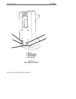
Figure 1-4 Vehicle Dock Front View
1-7
. . . . . . . . . . . . . . . . . . .
Figure 1-5 Vehicle Dock Back View
1-8
. . . . . . . . . . . . . . . . . . . .
Figure 1-6 Vehicle Dock Computer Holder
1-9
. . . . . . . . . . . . .
Figure 1-7 Single Dock With Computer and
Cable Connector
1-10
. . . . . . . . . . . . . . . . . . . . . . . . . . . . . . . . . . . .
Figure 1-8 Multidock With Computer and
Cable Connectors
1-11
. . . . . . . . . . . . . . . . . . . . . . . . . . . . . . . . . . .
Figure 1-9 Interface Connector
1-12
. . . . . . . . . . . . . . . . . . . . . . . .
Figure 1-10 Single Dock 9-Pin Male Connector
1-13
. . . . . . . . .
Figure 1-11 Single Dock 25-Pin Female Connector
1-15
. . . . . .
Figure 1-12 Multidock 9-Pin Female RS-485 Connector
1-17
.
Figure 1-13 Vehicle Dock 3-Pin Male Power Connector
1-18
. .
Figure 2-1 Single Dock Connectors
2-3
. . . . . . . . . . . . . . . . . . . .
Figure 2-2 Multidock Connectors
2-3
. . . . . . . . . . . . . . . . . . . . . .
Figure 2-3 Mounting Brackets For Single Dock
2-5
. . . . . . . . .
Figure 2-4 Mounting Brackets For Multidock
2-6
. . . . . . . . . .
Figure 2-5 Positioning the Mounting Clips
2-7
. . . . . . . . . . . . .
Figure 2-6 Attaching the Dock to the Mounting Brackets
2-8
Figure 3-1 Assembling the In-line Fuse Holder
3-7
. . . . . . . . .
Figure 3-2 Terminating Wire Ends
3-8
. . . . . . . . . . . . . . . . . . . .
Figure 3-4 Side Battery Terminal Posts
3-11
. . . . . . . . . . . . . . . .
Figure 3-5 Top Battery Terminal Posts
3-13
. . . . . . . . . . . . . . . . .
Figure 3-6 Stripping the Power Cable Jacket
3-14
. . . . . . . . . . .
Figure 3-7 Wiring Diagram for Installing a Printer
3-15
. . . . .
Figure 3-8 Installing the Power Cable In-Line
Noise Filter
3-17
. . . . . . . . . . . . . . . . . . . . . . . . . . . . . . . . . . . . . . . . .
Figure 3-9 Assembling Keyboard Tray
3-18
. . . . . . . . . . . . . . .
Figure 3-10 Attaching Dock to Tray
3-18
. . . . . . . . . . . . . . . . . .
Figure 3-11 Inserting Keyboard into Tray and
Attaching Cable to Computer
3-19
. . . . . . . . . . . . . . . . . . . . . . . .
Figure 3-12 Vehicle Dock Adjustable Mount Bracket
3-21
. . .
Figure 3-13 Vehicle Dock Adjustable Mount with
Computer Inserted
3-22
. . . . . . . . . . . . . . . . . . . . . . . . . . . . . . . . . . .
Figure 3-14 Vehicle Dock Adjustable Mount Back Side
3-23
.
Figure 3-15 Vehicle Dock Fixed Mount Bracket
3-24
. . . . . . . .
Figure 3-16 Vehicle Dock Fixed Mount Bracket Back Side
3-25
Figure 3-17 Vehicle Dock Fixed Mount with


