


SECTION 2
"
Installation Instructions
RT5900 SERIES Mobile Mount Radio Data Terminal
2-13
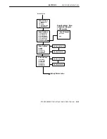
Instructions
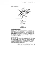
Mounting Bracket
Experiment with the terminal and the mounting bracket to determine the
bracket arrangement that will provide you with the best viewing angle. Use
two knobs and two lock washers on each side to attach the bracket to the
terminal. Use 3/8-inch hardware if you will be attaching the mounting
bracket to a desk, counter top, or shelving.
NC4000 Power Supply
Locate and identify the 10-foot external DC power cable (NPN:
216-860-001) in this kit along with the AC power cord. One end of the DC
power cable has a metal collar and plugs into the three-pin connector
(shown) on the NC4000 Power Supply.
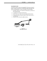
Connect the DC Power Cable
1. Align the pins and push the round connector into the power supply.
2. Screw the collar into place. Do not overtighten.
3. Route the cable toward the terminal.
4. Align the cable connector to the power jack and push the connector
firmly into the jack.
5. Turn the collar on this connector clockwise to lock it in place.
6. Use the cable clamps and screws in this kit to secure the cable, mak-
ing a neat installation.
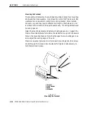
Connect the AC Power Cable
1. Plug the female end of this cable into the NC4000.
2. Plug the male end of this cable into a standard, grounded, three-prong
wall outlet.
Do not use an adapter to defeat the electrical ground.
The installation is complete.


