background image


14 

TVE-400/800-1600 H.264 IP Video Encoder User Manual 

Configuration 

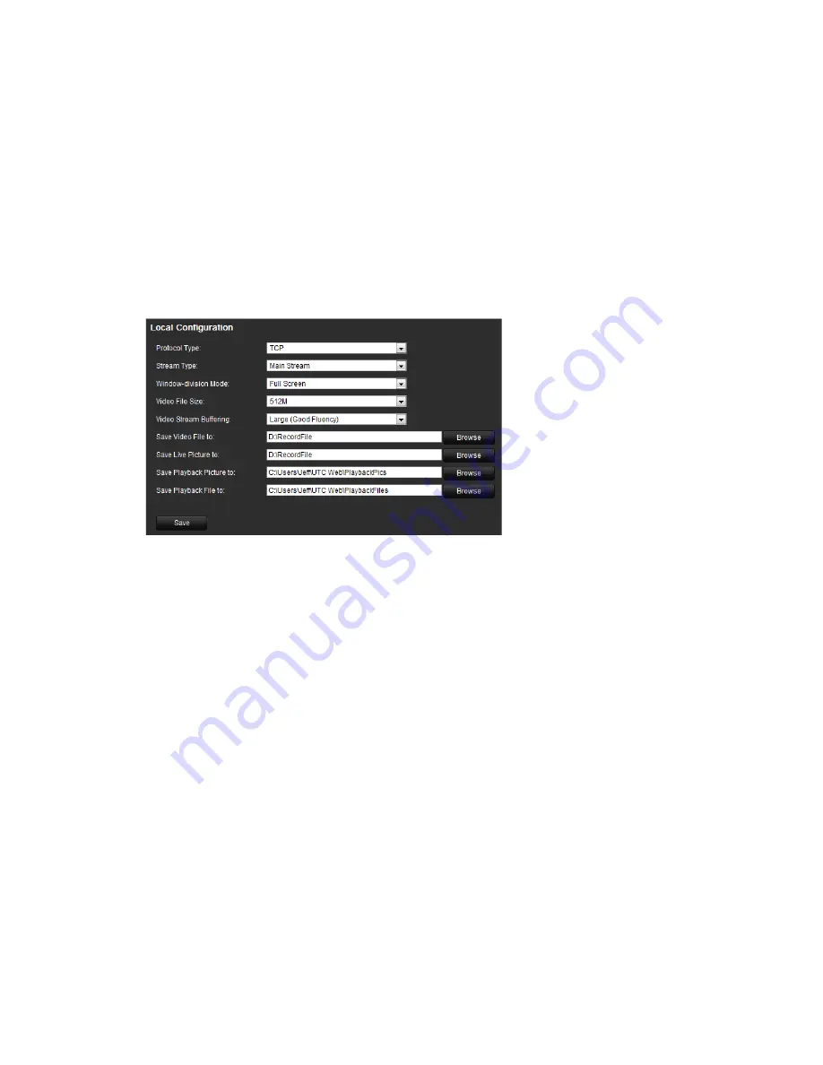
Local configuration 

Local configuration lets you define communication and network parameters such 
as protocol type, maximum file size, stream type and network transmission 
settings. You can also specify the directory locations for saving recorded and 
playback video, captured images, and downloaded files. 

To configure video loss detection: 

1.  Click 

Configuration 

>

 Local Configuration. 

The Local Configuration window 

appears. 


2.  Enter the required values. 

Protocol type

: Set the protocol type of stream transmission to TCP or UDP. 

UDP provides more real-time audio and video streams. TCP ensures the 
complete deliver of streaming data and better video quality but it may not 
always be reliable for real-time delivery. 

Stream type

: Select the stream type (main stream or sub stream) to be used 

for live view by the web browser.  

Window-division mode

: Select the window-division view mode to 4:3, 16:9 

or full-screen. 

Video file size

: Select the size of packed video files during manual recording 

to 256M, 512M or 1G.  

Video stream buffering

: Set the video buffering size to small (least latency), 

medium (balanced latency & fluency) or large (good fluency) to decrease 
latency or increase fluency for live view display performance.  

Save video file to

: Set the saving path for the manually recorded video files. 

Save live pictures to

: Set the saving path for the manually captured pictures 

in live view mode. 

Save playback picture to

: Set the saving path for the captured pictures in 

playback mode. 

Summary of Contents for TVE-1200

Page 1: ...TVE 400 800 1600 H 264 IP Video Encoder User Manual P N 1072585C EN REV 1 0 ISS 16OCT12...

Page 2: ...nt off and on the user is encouraged to try to correct the interference by one or more of the following measures Reorient or relocate the receiving antenna Increase the separation between the equipmen...

Page 3: ...ol 11 Video image settings 13 Configuration 14 Local configuration 14 Time settings 15 Network set up 16 Camera set up 21 Video streaming set up 22 Motion detection 23 Alarm input settings 27 Video lo...

Page 4: ...ii TVE 400 800 1600 H 264 IP Video Encoder User Manual Specifications 43...

Page 5: ...o encoder is shipped with the following items TVE encoder Power adaptor Power cable Quick start guide CD includes the user manual and TruVision Device Finder Key features The following key features ar...

Page 6: ...on It lights up green and flashes when data is being transmitted received It flashes at a faster rate when a large amount of data is being transmitted or received Figure 2 Back panel 4 channel 8 chann...

Page 7: ...ee Figure 2 on page 2 for information on connecting the power camera audio and network cables Alarm connections The TVE encoder supports the open close relay input as the alarm input mode When the ala...

Page 8: ...regulator 4 4N35 optocoupler 5 Relay output 6 Normal alarm 7 JQC 3FG 24 V relay The TVE encoder supports the open close relay input as the alarm output mode The alarm input can be selected to NO or NC...

Page 9: ...TruVision devices that support auto discovery anywhere on the network even in different subnets You can view and modify the IP address of any discovered device To install the TruVision Device Finder...

Page 10: ...e following shortcut on your desktop Figure 4 TruVision Device Finder shortcut icon To use the TruVision Device Finder 1 Double click the shortcut icon to open the tool The Start window appears 2 Clic...

Page 11: ...to be changed The key device characteristics for that device are listed in the right pane 4 Click Modify to change the IP address The IP address and device port address fields will be available to ch...

Page 12: ...ncoder The encoder s factory default user name is admin and the password is 1234 The encoder s factory default IP address is 192 168 1 70 Accessing the web browser To access the web browser 1 Open the...

Page 13: ...TVE 400 800 1600 H 264 IP Video Encoder User Manual 9 Menu tree Figure 5 Encoder menu tree...

Page 14: ...progress Description of live view Figure 6 Live view Item Name Description 1 Menu toolbar Lets you do the following View live video Play back video Search for event logs Configure settings Exit the i...

Page 15: ...currently selected camera adjust the speed of PTZ movement and turn on off the camera light and wiper To see live view 1 Open the encoder s web browser screen See Figure 6 2 Double click a camera fro...

Page 16: ...e encoder back panel Connect the R and R terminals of the PTZ camera or speed dome to the RS 485 T and RS 485 T terminals respectively Configure the RS 485 parameters under the Configuration Serial po...

Page 17: ...anually adjust the brightness saturation contrast and hue values of the camera image in order to get the best image quality 1 In the live view window click the Video Parameters button on the bottom ri...

Page 18: ...e deliver of streaming data and better video quality but it may not always be reliable for real time delivery Stream type Select the stream type main stream or sub stream to be used for live view by t...

Page 19: ...eras will synchronize automatically with the time server To configure time settings 1 Click Device Configuration Device Parameters Time Settings The Time Settings window appears 2 Select the time zone...

Page 20: ...ss and MTU You can also configure the DNS server PPPoE If the encoder is directly connected to ADSL modem configure the PPPoE settings Contact your ISP to get the user name and password DDNS If the en...

Page 21: ...4 subnet mask Enter the subnet mask for your network so the encoder will be recognized within the network Default value is 255 255 255 0 IPv4 default gateway Enter the IP address of your network gatew...

Page 22: ...he settings To configure e mail settings 1 Click the Device Configuration Network Settings Basic Settings to set the IPv4 Address IPv4 Subnet Mask IPv4 Default Gateway and the Preferred DNS Server 2 C...

Page 23: ...e configured with NAS or IP SAN mode 1 Click the Device Configuration Network Settings NetHDD Settings The NetHDD Settings window appears 2 Enter the IP address of the network storage system and file...

Page 24: ...Network Settings SNMP Settings The SNMP Settings window appears 2 Enter the NIC port value The default value is 161 3 When SNMPv1 and or SNMP v2c are enabled you can configure the read SNMP community...

Page 25: ...nt on screen You can add up to eight lines of text on screen This option can be used for example to display emergency contact details To configure the OSD settings 1 Click the Device Configuration Cam...

Page 26: ...e Configuration Camera Settings Text Overlay Settings The Text Overlay Setting window appears 2 Select a camera from the drop down list 3 Click the checkbox for a line of text and enter the characters...

Page 27: ...TSC PAL values are 704x576 704x288 352x288 or 176 x 144 Bit rate type Select variable or fixed bit rate Variable produces higher quality results suitable for video downloads and streaming Default is V...

Page 28: ...ra must be set up individually 3 Check Enable Motion Detection 4 Select the area sensitive to motion and the sensitivity level Click Start Draw Click and drag the mouse cursor across the screen The ar...

Page 29: ...tion can be recorded Click to set the time periods for the arming schedule during the day You can schedule up to eight time periods in a day Default is 24 hours Click OK Note Time periods defined cann...

Page 30: ...channel to trigger an external alarm output when a motion detection event occurs See To set up an alarm output below on how to set up an external alarm output Select the channel to trigger recording...

Page 31: ...an be configured to record when an alarm is triggered by an external alarm device for example PIR detector dry contacts To configure alarm inputs 1 Click Device Configuration Alarm Settings Alarm Inpu...

Page 32: ...output on how to set up an external alarm output Select the channel to trigger recording when a motion detection event occurs If the camera is PTZ select PTZ linking 6 Click Save to save settings Vide...

Page 33: ...e 23 for further information 5 Select the Linking Method tab Then select the response method to notify you of the alarm 6 Click Save to save the settings Tamper proof alarm Video tampering such as mov...

Page 34: ...fy you of the alarm 6 Click Save to save the settings System notification Setting up system notifications instructs the encoder to alert you when irregular events occur and how to alert you to the eve...

Page 35: ...remain hidden from view For example you can choose to block the view of a camera when overlooking residential premises This hidden area is referred to as privacy masking Privacy masking cannot be vie...

Page 36: ...Z unit To configure a privacy mask 1 Click Device Configuration Serial Port Settings RS 485 The RS 485 window appears 2 Enter the RS 485 parameters The default parameters are Baud rate 9600 Data bit 8...

Page 37: ...ording types to select for the schedule which are color coded Normal Blue Records continuously Motion Green Records only motion events Alarm Red Records only alarm events Motion Alarm Orange Records m...

Page 38: ...recording type This setting instructs the encoder to begin recording when an alarm is triggered The recording types available are Normal Motion Alarm Motion or Alarm Motion and Alarm Note If Motion A...

Page 39: ...ording schedule of a camera 2 Click Advanced in the Record Schedule window 3 Under Redundant Record select the Yes 4 Click OK Return to the Record Schedule window 5 Click Save to save the settings To...

Page 40: ...mera Operation There is no default user name and password The administrator must create the user name and password Guest The default guest user account includes access to remote view logs status and p...

Page 41: ...The User Information window appears 2 Click Modify The Modify User window appears 3 Modify the user information such as the user name and password user type and user s permissions under Basic Permiss...

Page 42: ...ary purposes 3 Calendar panel Select a date to playback recordings 4 Search panel Results of search displayed here 5 Timeline Allows you to jump forwards or backwards in time The timeline moves left o...

Page 43: ...Recording type Description of the color coding of recording types shown in the timeline Green indicates continuous recording Red indicates alarm event recording Yellow indicates motion recording 9 Tim...

Page 44: ...s 3 Under Major Type and Minor Type select an option from the drop down list The minor type list of options available depends on the option selected under major type 4 Click the Search button A list o...

Page 45: ...formation The Device Information window appears 2 Change the device name or number if required 3 Click Save to save the settings Restarting the device To restart the encoder 1 Click Configuration Main...

Page 46: ...To import files under Import Parameters click Browse to locate the file to be imported from a local back up device Click Import to start importing Upgrading the system The encoder firmware can be upg...

Page 47: ...8 kbps or user defined Max 3072 kbps Stream type Video Video Audio Audio bit rate 64 kbps Dual stream Support External interface Network interface 1 RJ45 10 M 100 M adaptive Ethernet interface Serial...

Page 48: ...ent Max 1 5 A Operating temperature 10 to 55 C 14 to 131 F Operating humidity 10 to 90 Dimensions 315 45 201 mm 12 4 1 77 7 91 in Weight 1 5 kg 3 3 lb Model TVE 1600 Video Audio input Video compressio...

Page 49: ...t 1 RJ45 10 M 100 M adaptive Ethernet port Serial port 1 RS 485 port half duplex Alarm in 4 Alarm out 1 Others Protocol Support CGI PSIA and ONVIF Current Max 2A Operating temperature 10 to 55 C 14 to...

Page 50: ...46 TVE 400 800 1600 H 264 IP Video Encoder User Manual...

Reviews: