background image


10 

Installation Guide 

The visible IR range may vary due to multiple factors, such as weather, IR 

reflection, 

rate of viewing objects, lens adjustment

, and camera settings. 

Please refer to the camera datasheet for the standard IR range.


Note

Avoid installing the IR camera 

near large items, such as, a tree or 

wall. The


reflection will cause over

-exposure and 

impact the quality of the 

image. 

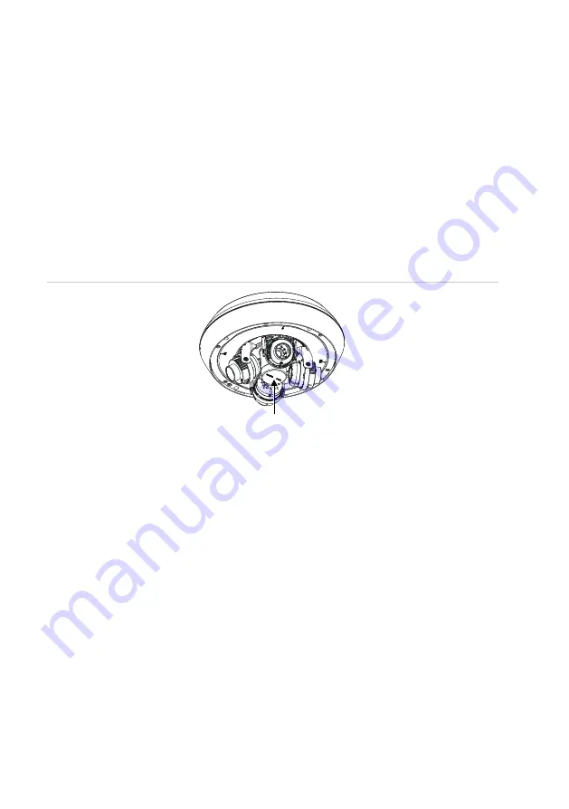
Accessing the micro SD/SDHC/SDXC slot 

Remove

 the camera cover ring and insert 

a micro SD/SDHC/SDXC card 

in the slot 

for local storage as a backup in case the network fails. 

The 

micro 

SD

 card is NOT 

supplied with the camera.


Figure 2: Access the micro SD card in the camera 


SD card cover


Video and log files stored on the m

icro SD card can


only


be accessed via 

the 

web browser. You

 can access video from the card using TruVision 

Navigator or a recording device

, but log files must be accessed via the 

web browser interface

Mounting accessories 

The camera can be installed on a cup base (included with the camera) 

and then attached to a TruVision 

wall or pendant mount, which are s

old 

separately

Note

: The 

wall and pendant mounts


are shipped with installation 

hardware

.  

TruVision Multi-imager camera pendant mount (TVMI-PM) 

The multi-imager 

camera can be installed on 

a TVMI-PM pendent mount. 

The mount length is 116.5 × 57 mm (4.59 × 2.24 in.). 


Summary of Contents for TruVision Multi-Imager

Page 1: ...TruVision 20MP 4 x 5MP 360 Degree Multi Imager Camera Installation Guide P N 1073687 EN REV A ISS 20FEB20...

Page 2: ...mits are designed to provide reasonable protection against harmful interference when the equipment is operated in a commercial environment This equipment generates uses and can radiate radio frequency...

Page 3: ...disposed of as unsorted municipal waste in the European Union For proper recycling return this product to your local supplier upon the purchase of equivalent new equipment or dispose of it at designa...

Page 4: ...E THAT ANY PERSON OR ENTITY BUYING ITS PRODUCTS INCLUDING ANY AUTHORIZED DEALER OR AUTHORIZED RESELLER IS PROPERLY TRAINED OR EXPERIENCED TO CORRECTLY INSTALL FIRE AND SECURITY RELATED PRODUCTS For mo...

Page 5: ...e 3 Package contents 4 Cable requirements 5 Camera description 6 Install the camera 7 IR illuminators 9 Accessing the micro SD SDHC SDXC slot 10 Mounting accessories 10 Install the camera to a mount 1...

Page 6: ...in several languages on the EMEA web site Installation This chapter provides information on how to install the camera Installation environment When installing your product consider these factors Elect...

Page 7: ...the instructions in this manual when removing the camera cover Refer all servicing to qualified service personnel Cleaning Do not touch the bubble with fingers If cleaning is necessary use a clean clo...

Page 8: ...nit is returned it must be shipped back in its original packaging Camera Cup base Torx wrench G3 4 cable gland Used on the bubble assembly Screws Water joint Drywall anchor 6 x 29mm 4 pcs Screw M4 9 8...

Page 9: ...rce of the required output rating as listed on the unit Cable requirements For proper operation adhere to the following cable and power requirements for the cameras It is recommended to use CAT 5 cabl...

Page 10: ...E and network port 4 Power 12 VDC 5 Alarm input output 1 6 Alarm input output 2 7 RS 485 port 8 Audio out 9 Audio in 10 Lens 11 IR transparent cover 12 Camera positioning tray 13 Lens 14 Reset button...

Page 11: ...ase as a template to mark the mounting holes b If running the cables in to the side of the camera install the cable gland into the side of the camera base 2 Install the camera base to the ceiling a Ro...

Page 12: ...ate the camera body to the end according to the direction arrow below Make sure the mark of the camera body is aligned with the Lock mark of the camera base 3 Insert the screws to secure the camera bo...

Page 13: ...ubble assembly to the camera body IR illuminators The camera s built in IR illumination provides high quality video in low light environments even when there is no other illumination available You can...

Page 14: ...The micro SD card is NOT supplied with the camera Figure 2 Access the micro SD card in the camera SD card cover Video and log files stored on the micro SD card can only be accessed via the web browse...

Page 15: ...length is 116 5 200 mm 4 59 7 87 in Pendent mount Example Pendent mount with camera TruVision Multi imager camera pendent mount TVMI PM3 The multi imager camera can be installed on a TVMI PM3 pendent...

Page 16: ...Extension pipe Example Pendent mount and extension pipe with camera For further information please refer to the TruVision Multi imager Camera Mount Installation Guide TruVision Multi imager camera wal...

Page 17: ...1 Install the camera base to the cup base using the screws provided 2 Route the cables 3 Attach the cup base to the mount and tighten the screw on the mount to secure the camera to the mount Attach th...

Page 18: ...the catches in the camera base and body are correctly aligned Then push the camera body upward c Rotate the camera body to the end according to the direction arrow below Make sure the mark of the came...

Page 19: ...NVR in order to be operated by TruVision Navigator Please refer to the TruVision Navigator user manual for instructions on operating the camera with TruVision Navigator Specifications Electrical Volt...

Page 20: ...eight wires on a standard UTP STP cable and each wire is color coded The following shows the pin allocation and color of straight and crossover cable connection Figure 3 Straight through cable 1 White...

Page 21: ...2 Orange Orange 2 3 White Green White Green 3 4 Blue Blue 4 5 White Blue White Blue 5 6 Green Green 6 7 White Brown White Brown 7 8 Brown Brown 8 Please make sure your connected cables have the same...

Page 22: ......

Reviews: