


After entering the password, the main screen appears as
Figure 8 shows.
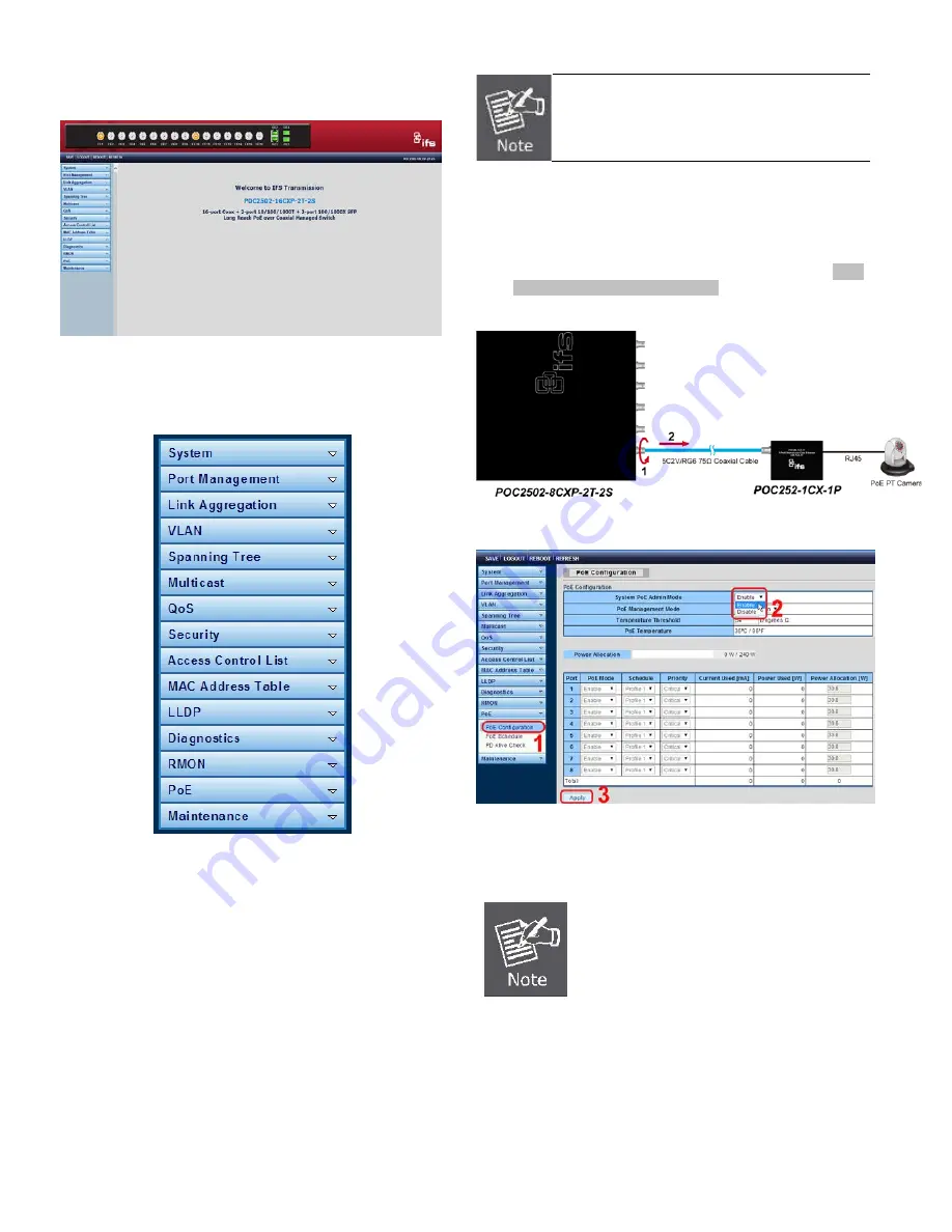
Figure 8:
Web Main Screen of POC2502 Managed Switch
The Switch Menu on the left of the Web page lets you access
all the commands and statistics the POC2502 Managed Switch
provides.
Figure 9:
Switch Menu
Now, you can use the Web management interface to continue
the Switch management.
Please refer to the user’s manual for more information.
Now, you can use the Web management interface to continue
the Switch management. For more detailed switch
configuration, please refer to the user’s manual.
Starting Long Reach PoE Communication
The following shows how to start up the
Long Reach PoE
Communication
of the POC2502 Managed Switch from Web
Management.
T
he POC2502 Managed Switch is configured
DISABLED
Long Reach PoE function as default.
Connect the Coaxial Cable
1.
Insert the coaxial cable with one side being the
75ΩBNC
plug connector into the Long Reach Ethernet coaxial
interface.
2.
Connect the other end of the cable to a device with Long
Reach Ethernet coaxial Extender installed.
3.
Tight the BNC male connector gently.
4.
Enable Long Reach Power over Ethernet function for the
all POC2502 ports from Web UI.
5.
Check the LNK LED of the Long Reach Power over
Ethernet interface on the front of the POC2502 Managed
Switch. Ensure that the Long Reach Power over
Ethernet interface is operating correctly.
1. Before installation, please consider the
distance and watts value demand for PD
devices. The POC2502 Managed Switch
and POC2502 Extender PoE output
capacity
and upload
/ download
performance depend on the length of
coaxial cable. You can refer to user
manual chapter 1.5 for more information.
2. As there are various resistance values in
the category of RG-59/U or RG-6/U
cable, the actual data rate will vary on
the quality of the copper wire and
environmental factors.
4
IFS POC2502 Series Quick Start Guide


