background image

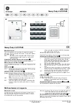
NX-148E- RF LCD Touchpad w ith Receiver Installation Instructions 

13 

Zone _____ 
 

Assigned to 
module #_____. 


RM    HE    P 


1 - Enable  sensor 


2 - Supervised 


3 - Fire 

supervision 


4 - Input option 1 


5 - Input option 2 

6 - 8 Not used 


Partition 1 keyfob 


Partition 2 keyfob 


Partition 3 keyfob 


Partition 4 keyfob 


Partition 5 keyfob 


Partition 6 keyfob 


Partition 7 keyfob 


Partition 8 keyfob 

593 
Receiver Options 
(all defaults off)  


1 - Enable  jam 

  2 - Enable 

auto advance to next 
zone number  


3 - Keyfob user ID  

(off all keyfobs report 
as user 99; on = 
keyfob reports as 
learned zone #) 

4-5 Not used  


6 - keyfob disarm 

only during entry or 
partial alarm 

7-8 Not used 

None 


594 
Receiver Zone 
Bank Setting 
(Default = 0

—set 

this before 
learning any 
sensors. See step 
5 under Enrolling 
w ireless sensors) 

Starting zone numbers 
by bank setting: 


0 = 1  


1 = 9  


2 = 17  


3 = 25 


4 = 33  


5 = 41  


6 = 49  


7 = 57  


8 = 65  


9 = 73 | 


10 = 81  


11 = 89  


12 = 97  


13 = 105  


14 = 113  


15 = 121  


16 = 129  


17 = 137  


18 = 145  


19 = 153  


20 = 161  


21 = 169  


22 = 177  


23 = 185  


595 
Supervision 
Window s 

Normal ______hours. 
(0 to 255 hours; 
default = 24 hours) 

Fire ______hours. 
(0 to 255 hours; 
default = 4 hours) 

Segment 3: 

Transmitter Check-in Window  ____minutes 
(1 to 30 minutes, default = 40 minutes, disabled) 

Do not change Segment 3 setting unless 
required. See step 7 under 

Transmitter 

supervision w indow s

600 
Number of rounds 
received from last 
transmitter 
learned 

See 

Transmitter testing

Summary of Contents for NX-148E-RF

Page 1: ...8E NX 8V2 NX 6V2 or NX 4V2 and downloading via modem make sure the control panel version is equal to or greater than the following versions NX 8E 17 00 NX 8V2 1 04 NX 6V2 1 05 NX 4V2 1 04 Make sure yo...

Page 2: ...18 2000 ft 610 m 16 2500 ft 760 m 16 7 Run the antenna wires through the antenna holes in the mounting plate Figure 2 and into the wall 8 To mountthe touchpad to the mounting plate place the top of t...

Page 3: ...bank Location 594 The bank setting is based on the zone capabilities ofboth the receiver and the panel and mustbe set before you add learn transmitters 6 Enter 400 to enter the sensor transm itter le...

Page 4: ...er will be displayed for the keyfob partitions Press the partition number to toggle the partition on and off 6 To continue programming keyfob transmitter partition settings repeatsteps 4 to 8 7 To exi...

Page 5: ...Note Press repeatedlyto scroll through available functions Table 4 Touchpad functions Function number Function 0 Adjust touchpad tone 1 Temp master mode View zone status 2 Service menu 3 View alarmmem...

Page 6: ...ss or to turn the selected device on or off 4 Repeatsteps 2 and 3 until all devices have been programmed 5 To exit press Unit and house codes for X10 47 To program the specific X10 unit and house code...

Page 7: ...the central monitoring station Open 75 9 25 17 57 P3 Table 10 lists some ofthe possible eventlog messages Adjust view brightness ofLCD 91 To adjustthe view and brightness ofthe LCD display do the fol...

Page 8: ...ge Enables custommessage display 10 Clock Enables clockdisplay 11 Custom message lock Prevents over writing the custom message during touchpad copy 12 Select an option Programs specialcharacteristics...

Page 9: ...the tampered zone Zone low battery press A w ireless devicehas a low battery Press to identify the zone Zone lost press A w ireless or multiplexed zone device is not reporting to the control Press to...

Page 10: ...ob Partition 8 keyfob Zone _____ Assigned to module _____ RM HE P 1 Enable sensor 2 Supervised 3 Fire supervision 4 Input option 1 5 Input option 2 _ 6 8 Not used Partition 1 keyfob Partition 2 keyfob...

Page 11: ...Partition 2 keyfob Partition 3 keyfob Partition 4 keyfob Partition 5 keyfob Partition 6 keyfob Partition 7 keyfob Partition 8 keyfob Zone _____ Assigned to module _____ RM HE P 1 Enable sensor 2 Supe...

Page 12: ...Partition 2 keyfob Partition 3 keyfob Partition 4 keyfob Partition 5 keyfob Partition 6 keyfob Partition 7 keyfob Partition 8 keyfob Zone _____ Assigned to module _____ RM HE P 1 Enable sensor 2 Supe...

Page 13: ...sor 2 Supervised 3 Fire supervision 4 Input option 1 5 Input option 2 _ 6 8 Not used Partition 1 keyfob Partition 2 keyfob Partition 3 keyfob Partition 4 keyfob Partition 5 keyfob Partition 6 keyfob P...

Page 14: ...temperature 30 to 140 F 34 to 60 C Humidity 90 relative noncondensing Dimensions 5 x 6 x 1 in 12 7 x 15 2 x 2 5 cm Regulatory information FCC compliance This device complies w ith part 15 of the FCC...

Reviews: