P/N 1073029-EN
• REV
A
• ISS
03JUN15
3 / 6
Caution
: The RS
-
232 serial port on the camera is not a
network connection.
8.
Re
-attach the bubble
by screwing it
to the housing.
9.
See “Accessing the camera over the internet
” on page 4 to
configure the camera over the internet. Refer to the
Configuration Manual for detailed information.
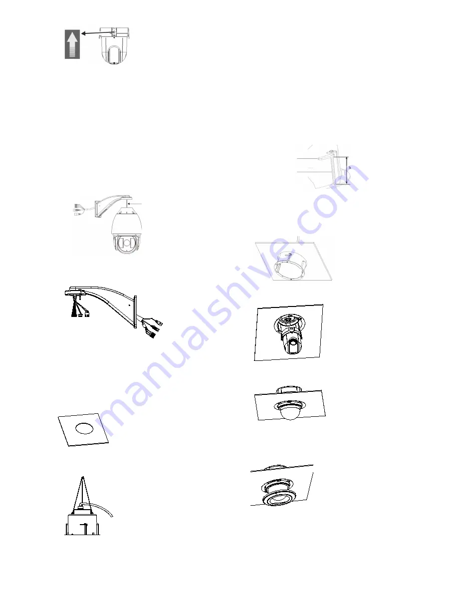
TVP-1122/3122 pendant-mount camera
1.
Prepare the mounting surface and install the camera
bracket.
2.
Attach the safety cable to the bracket and
then route the
cables from the pendant bracket as shown below.
Safety cable
3. C
onnect the cables to the PCB of the module through the
cable entry hole on top of the housing.
4.
See “Accessing the camera over the internet
” on page 4 to
configure the camera over the internet. Refer to the
Configuration Manual for detailed information.
Flush-mount camera
1. Drill a hole on the ceiling using
the drill template
.
2.
Tie three safety cables (not supplied) to the safety hooks
on the camera and hang the camera from a secure point.
3.
Unscrew
the bubble
from the camera and remove the
protective tape from the PTZ module.
4.
Press the two tabs on either side of the PTZ module and
remove it from the camera housing.
5.
Route the cables from the bracket and connect them
to
the PCB of the module through the cable entry hole on
the
top of the housing
.
Note
: If alarm
and audio input/output
relays are to be used
, also
connect them to the PCB of the module.
6.
Adjust the height of the two
housing tabs
by
turning the
screw
on which they are attached
. The distance (h)
of
the
tabs
from
the housing ring must be
greater than the
thickness of
the ceiling.
Housing tab
Screw
7. Make sure the housing tab is closed
and then PUSH the
housing into the pass-through hole. Hold the housing and
fix
it by screwing the housing tabs down
to the mounting
surface
8.
Insert the PTZ module into the housing:
9.
Re
-attach the bubble
by screwing it
to the housing.
10.
Install the trim ring. Align the trim ring to the housing, and
insert the fix
-pins to the holes. Then rotate the ring
clockwise to secure.
11.
See “Accessing the camera over the internet
” on page 4 to
configure the camera over the internet. Refer to the
Configuration Manual for detailed information.
RED
AC2
4V
YELLOW/
GR
EE
N
BLA
CK
AC2
4V


