


P/N 1077877
• REV 2 • ISS 19MAR19
5 / 6
bar LED graph should either be OFF or only the first LED
should be intermittently ON.
2. Conduct a series of impacts along the protected surface
while observing the bar LED graph. Look for a response
on the bar LED that illuminates the first 4 red LEDs, plus
the yellow and green LEDs and 1 to 3 of the upper level
red LEDs. Ideally, the 10th LED will not illuminate. (The
yellow LED indicates the signal is near the alarm
Threshold, and the Green LED indicates the signal has
exceeded the Threshold.)
3. If the signal response always illuminates the 10th LED,
lower the Gain 1 level and repeat the test OR if the signal
response does not illuminate the Green LED and at least 1
of the upper red LEDs, increase the gain 1 level and
repeat the test. When the response is consistently above
the Green LED and at, or below, the 10th red LED, the
Gain is optimized for the installation.
Setting the Climb alarm parameters (sustained attack)
1. Use S1 to set the Climb time parameter (the duration of a
sustained attack that must occur within the Time Window
to cause an alarm).
2. Use S2 to set the Time Window (the period in which the
time specified by the Climb setting must accumulate, or
the time in which the specified number of Cuts must occur
to cause an alarm).
3. Conduct a series of simulated attacks along the protected
surface while observing the bar LED graph. If the sensor
does not detect and alarm for some of the simulated
attacks, raise the Gain 1 level and repeat the tests.
4. If the attack simulations always cause alarms, use these
settings and monitor the system for nuisance alarms. If the
nuisance alarm rate (NAR) is too high, lower the Gain 1
level.
5. Repeat this process until the sensor always detects the
simulated attacks, and the NAR is acceptable.
Setting the Cut alarm parameters (impact attack)
1. Use S3 to set the number of impacts required to cause an
alarm (the impacts must occur within the Time Widow
setting).
2. Simulate a series of impact attacks along the protected
surface while observing the bar LED graph. Look at the
bar LED for a response that is above the Threshold
(Green LED ON) for each impact.
3. If the impact attack simulations always cause alarms, use
these settings and monitor the system for nuisance
alarms. If the nuisance alarm rate (NAR) is too high, lower
the Gain 1 level. If the processor does not always alarm
for the impact attack simulations raise the Gain 1 level.
4. Repeat this process until the sensor always detects the
simulated attacks, and the NAR is acceptable.
Connecting the Universal Configuration
Module
For UCM calibration, set switch S5-4 to OFF, and cycle the
power.
Switch 5-4 must be OFF to operate with UCM configuration
parameters.
Remove the enclosure cover and connect the UCM computer
to the processor via USB (T1).
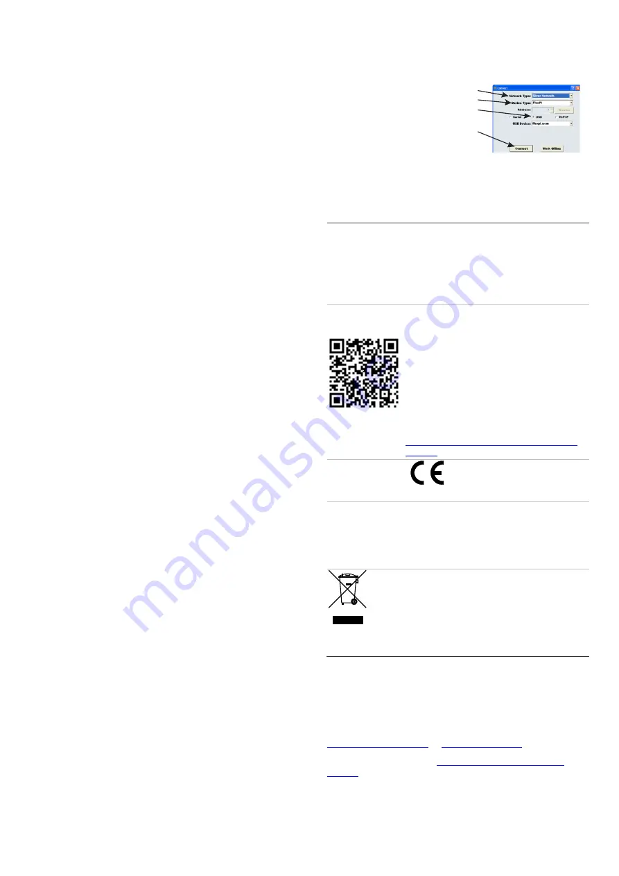
Start the UCM software (the UCM Connect dialog displays).
The FlexPI Status window opens.
Select the Network Type: Silver Network
Select the Device Type: FlexPI
Select the connection type USB
Select Connect to establish a
connection to the processor
Note:
Select F1 to launch the UCM online help file.
Regulatory information
Manufacturer
PLACED ON THE MARKET BY:
UTC Fire & Security Americas Corporation, Inc.
3211 Progress Drive, Lincolnton, NC, 28092,
USA
AUTHORIZED EU REPRESENTATIVE:
UTC Fire & Security B.V.
Kelvinstraat 7, 6003 DH Weert, Netherlands
Product warnings
and disclaimers
THESE PRODUCTS ARE INTENDED FOR
SALE TO AND INSTALLATION BY QUALIFIED
PROFESSIONALS. UTC FIRE & SECURITY
CANNOT PROVIDE ANY ASSURANCE THAT
ANY PERSON OR ENTITY BUYING ITS
PRODUCTS, INCLUDING
ANY “AUTHORIZED
DEALER” OR “AUTHORIZED RESELLER”, IS
PROPERLY TRAINED OR EXPERIENCED TO
CORRECTLY INSTALL FIRE AND SECURITY
RELATED PRODUCTS.
For more information on warranty disclaimers and
product safety information, please check
https://firesecurityproducts.com/policy/product-
warning/
Certification
European Union
directives
UTC Fire & Security hereby declares that this
device is in compliance with the applicable
requirements and provisions of the Directive
2014/30/EU and/or 2014/35/EU. For more
information see www.utcfireandsecurity.com or
www.interlogix.com.
2012/19/EU (WEEE directive): Products marked
with this symbol cannot be disposed of as
unsorted municipal waste in the European Union.
For proper recycling, return this product to your
local supplier upon the purchase of equivalent
new equipment, or dispose of it at designated
collection points. For more information see:
www.recyclethis.info
Additional information
For further details on the products, please refer to the product
information included in the UCM software CD (DF950CM).
For contact information see our Web site:
or
For customer support, see
Copyright © 2011 UTC Fire & Security. All rights reserved.


