background image

2  

Concord 4 Touch Screen Installation Sheet 

Table 2: Maximum SuperBus Lengths 

Wire gauge 
(shielded or 
unshielded) 

Max. touch screen wire length between touch 
screen and panel 

22 

120 feet 

• 

Depending on system loading, multiple touch screens can 
be installed on a Concord 4 system. See the examples in 
Table 3 and Table 4. 

Table 3: Example - Concord 4 system with three Concord 4 touch 
screens and one alphanumeric touch pad 

Device 

Part # 

Number 
used 

Alarm 
mA 
current 
draw 

Available 
Power 

Concord 4 


1000mA 

Concord 4 
Touch 
Screen 

60-924-3-
C4TS 

750mA 


ATP 1000  

60-983 

110mA 


140mA 
remaining 

Table 4: Example - 

Concord 4 system with eight Concord 4 

touch screens, one alphanumeric touch pad, and panel voice           
(Note: SB 2000 power supply is needed) 

Device 

Part # 

Number 
used 

Alarm 
mA 
current 
draw 

Available 
Power 

Concord 4 


1000mA 

SB2000 
voice only 
module 

60-836 

600mA 


Concord 4 
Touch 
Screen 

60-924-3-
C4TS 

250mA 


ATP 1000 

60-983 

110mA 


40 mA 
remaining 

SB 2000 
Power 
Supply 

600-1019 


2000mA 

Concord 4 
Touch 
Screen 

60-924-3-
C4TS 

1750mA 


250mA 
remaining 

Installing the mounting plate  

To mount the touch screen: 

1.  Remove the touch screen from the mounting base by 

inserting a small screwdriver into the opening slot on the 
bottom of the touch screen (Figure 1). 

Figure 1: Opening slot 


2.  Hold the base on the wall at the desired mounting location 

and mark the mounting holes and bus wire drop. 

3.  At the mounting hole locations, drill 1/8-inch holes into the 

wall for plastic anchors.  

4.  At the bus wire drop opening, drill a 1/2-inch hole into the 

wall. 

5.  Push the two plastic anchors into the drilled holes and 

tighten screws within a quarter-inch of the anchors. 

6.  Feed the bus wiring through the bus wire drop in the 

mounting base (Figure 2). 

Figure 2:  Mounting 


7.  Hang the base over the screws, level the base, and 

tighten the screws. 

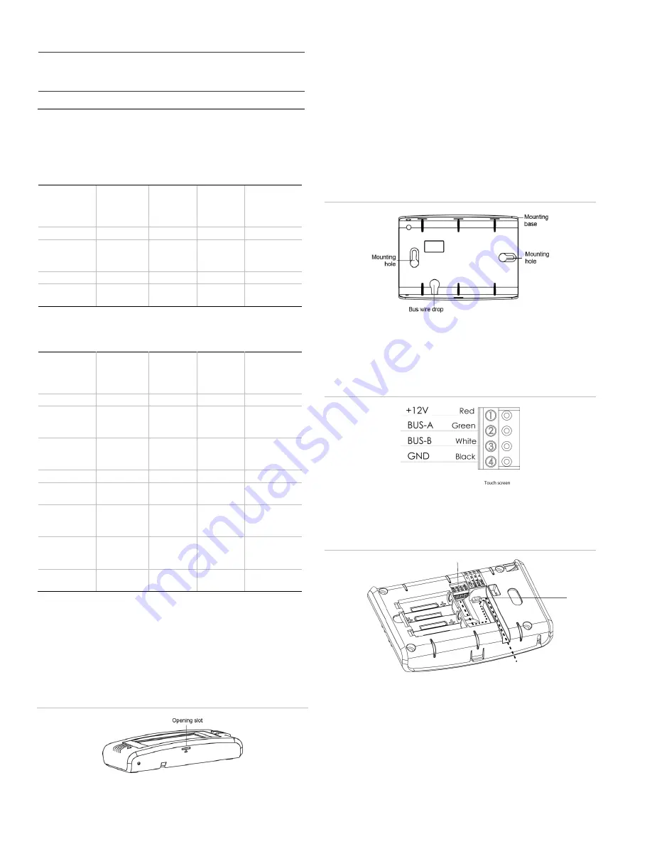
8.  Connect the bus wires to the 4-position pluggable 

(removable) terminal block (Figure 3). 

Figure 3: Connecting the touch screen 


9.    Plug the terminal block into the touch screen and secure 

the bus wires to the tie wrap loop with the tie wrap 
provided (Figure 4). 

Figure 4: Plug terminal block into touch screen 


10.  Angle the top of the touch screen into the hooks on the top 

of the base.  

11.  Start feeding the bus wires through the bus wire drop, and 

swing the bottom of the touch screen into the lower part of 
the base until there is an audible click. 

Note: 

If necessary, use a soft cloth to clear smudges on 

the touch screen. Do not use glass cleaner. 

Terminal block 

Tie wrap 
loop 

Bus wires 

Summary of Contents for 60-924-3-C4TS

Page 1: ...oires produit contient des éléments qui pourraient être les dangers d étouffement Veuillez garder hors de la portée des jeunes enfants WARNING Disconnect panel power before servicing Débrancher l alimentation du panneau avant l entretien CAUTION Use static electricity precautions when handling electronic components Utiliser les précautions de l électricite statique lors de la manipulation des comp...

Page 2: ...e by inserting a small screwdriver into the opening slot on the bottom of the touch screen Figure 1 Figure 1 Opening slot 2 Hold the base on the wall at the desired mounting location and mark the mounting holes and bus wire drop 3 At the mounting hole locations drill 1 8 inch holes into the wall for plastic anchors 4 At the bus wire drop opening drill a 1 2 inch hole into the wall 5 Push the two p...

Page 3: ... and battery power from the panel 5 Replace the defective bus device with a new one 6 Apply AC and battery power to the panel Partition assignment With this menu assign bus devices to work in the desired partition To assign bus devices to partitions 1 With the display showing the desired bus device press 2 Press A or B until the display shows DEVICE PTN and then press The display shows PARTITION A...

Page 4: ...ate the touch screen touch the icons in the corners of the screen using a soft fine point If unable to access calibration using the above procedure use the following steps 1 Press and hold the Reset button Figure 5 Figure 5 Touch screen reset button 2 Press and hold anywhere on the screen 3 While pressing the screen release the Reset button 4 Follow the calibration prompts Help Touch the Help butt...

Page 5: ...ress volume levels in settings Check for correct wiring connections at touch screen and panel terminals Sensors named as door window motion are displaying under Property icon The name of the sensor is too long Place door window motion earlier in the name or shorten the name Touch screen has red icon offline This icon is displayed if a touch screen has incurred some form of communication and or har...

Page 6: ...Class B digital apparatus complies with Canadian ICES 003 Cet appareil numérique de la classe B est conforme à la norme NMB 003 du Canada Warranty Information MANUFACTURER HEREBY DISCLAIMS ALL WARRANTIES AND REPRESENTATIONS WHETHER EXPRESS IMPLIED STATUTORY OR OTHERWISE INCLUDING BUT NOT LIMITED TO ANY WARRANTIES OF MERCHANTABILITY OR FITNESS FOR A PARTICULAR PURPOSE WITH RESPECT TO ITS CONCORD 4 ...

Reviews: