


XMU+ Installation Handbook rev.06
29
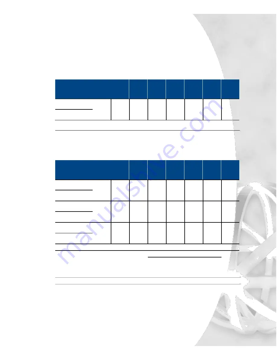
Common Interface Tables (By Application)
GPT iSDX and Realitis; Siemens 9005-9006, HiPath 3000/4000;
Intecom; ITT 3100; HICOM 300 Series; Mitel SX50, SX200,
SX2000; Toshiba Perception Rolm 9751, CBX 8000, CBX 9000;
TadarianCoral.
PABX
Announcer
Line 1
Line 2
Line 3
Line 4
Line 5
Line 6
Line 7
Line 8
Pin-
Pin-
Pin-
Pin-
Pin-
Pin-
Pin-
Pin-
Signal
Signal
Color
Color
Color
Color
Color
Color
Color
Color
Ring
Ring
1 - Blu/
4 - Brn/
7- Org/
10 - Slt/
13 - Grn/
16 - Blu/
19 - Brn/
22 - Org/
Wht
Wht
Red
Red
Blk
Yel
Yel
Vlt
26- Wht/
29 -Wht/
32 Red/
35 - Red/
38 - Blk/
41 - Yel/
44 - Yel/
47 - Vlt/
Tip
Tip
Blu
Brn
Org
Slt
Grn
Blu
Brn
Org
PBX Operation Mode: Ring Start (R).
GPT iSDX and Realitis use the 1HAC 50049 ADB card to interface.
AT&T Dimension 2000
PABX
Announcer
Line 1
Line 2
Line 3
Line 4
Line 5
Line 6
Line 7
Line 8
Pin-
Pin-
Pin-
Pin-
Pin-
Pin-
Pin-
Pin-
Signal
Signal
Color
Color
Color
Color
Color
Color
Color
Color
Ring
Ring
1 -
4 -
7 -
10 -
13 -
16 -
19 -
22 -
Blu/Wht
Brn/Wht
Org/Red
Slt/Red
Grn/Blk
Blu/Yel
Brn/Yel
Org/Vlt
26 -
29 -
32 -
35 -
38 -
41 -
44 -
47 -
Tip
Tip
Wht/Blu
Wht/Brn
Red/Org
Red/Slt
Blk/Grn
Yel/Blu
Yel/Brn
Vlt/Org
Battery
Start-
28 -
31 -
34 -
37 -
40 -
43 -
46 -
49 -
*
Wht/Grn
Red/Blu
Red/Brn
Blk/Org
Blk/Slt
Yel/Grn
Vlt/Blu
Vlt/Brn
3 -
6 -
9 -
12 -
15 -
18 -
21 -
24 -
S2
Start+
Grn/Wht
Blu/Red
Brn/Red
Org/Blk
Slt/Blk
Grn/Yel
Blu/Vlt
Brn/Vlt
AL1
CP1
27 -
30 -
33 -
36 -
39 -
42 -
45 -
48 -
Wht/Org
Wht/Slt
Red/Grn
Blk/Blu
Blk/Brn
Yel/Org
Yel/Slt
Vlt/Grn
2 -
5 -
8 -
11 -
14 -
17 -
20 -
23 -
Battery
CP2
*
Org/Wht
Slt/Wht
Grn/Red
Blu/Blk
Brn/Blk
Org/Yel
Slt/Yel
Grn/Vlt
PBX Operation Mode: Pulse Start/Level Return (PS/LR NC).
Set the switches on the LC 13 circuit pack as follows:
Circuit 0
Circuit 1
Switch 4 - Open
Switch 1 - Open
Switch 5 - Closed
Switch 2 - Closed
Switch 6 - Open
Switch 3 - Open
Connect announcer to Dimension 2000 LC13 Circuit Pack, Recorded Announcement Interface.
Summary of Contents for XMU+
Page 1: ...Installation Handbook...
Page 6: ...iv Table of Contents...
Page 8: ...2 Chapter 1 Before You Start...
Page 14: ...8 Chapter 1 Before You Start...
Page 16: ...10 Chapter 2 Installing the XMU...
Page 20: ...14 Chapter 3 Applying Hardware Settings to XMU Line Cards...
Page 26: ...20 Chapter 3 Applying Hardware Settings to XMU Line Cards...
Page 28: ...22 Chapter 4 Cabling the XMU...
Page 49: ...Recording and playing a 5 message from the front panel...
Page 50: ...44 Chapter 5 Recording and playing a message from the front panel...
Page 52: ...46 Chapter 5 Recording and playing a message from the front panel...
Page 53: ...Setting line card operating 6 mode...
Page 54: ...48 Chapter 6 Setting line card operating mode...
Page 58: ...52 Chapter 7 XMU Approvals...