Hardware Quick Installation Guide
1.
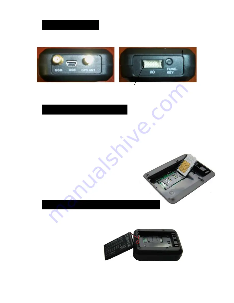
Introduction
Front Panel: Rear Panel:
Power Connector Function Key
2.
Insert the SIM Card
Please follow the steps below to insert the SIM Card correctly.
a.
Ensure the Sim Card is NOT pin locked
b.
Unscrew the back cover of device and pull out the lid by sliding lock to the right.
c.
Lift up the battery (if the battery is connected to the device)
d.
Unlock the SIM card slot by sliding the holder toward the “OPEN” direction.
e.
Place the SIM card into the SIM card holder.
f.
Lock the SIM card slot by sliding the holder toward the “LOCK” direction.
g.
Then, put back the battery and screw the back cover of the device.
Please ensure the SIM card is well placed in the holder and
well contacted; otherwise, the device might not detect
the SIM card successfully.
3.
Insert the backup battery
Please follow the steps below to insert the backup battery correctly.
a. Unscrew the back cover of device and pull out the lid by sliding lock to the right.
b. Connect the cable to the socket in the corner and place the battery .
c. Then, put the cover of the device back and screw it in.