1485 Jacobs Rd.
Deland, FL 32724
386.738.7307
P/N 53-00549-100 Rev. C 032619
www.intellitec.com
Intellitec
SERVICE MANUAL
SMART EMS
TM
The Service Select button allows the current threshold to be set to either 30 Amps or 20 Amps, to match the incoming
service. If the pictured adaptor is used on the incoming service, press the service select button to select the 20 Amp mode.
When power is first applied, the system will always be in the 30 Amp mode. The 30/20 Amp indicator LED will be on when
the system is in the 30 Amp mode. Momentarily pressing this button will switch the system to the 20 Amp mode.
Momentarily pressing this button again will switch the system back to the 30 Amp mode.
This panel can also be used to display the value of current stored in memory for
each of the four loads. To display the values of current stored in memory for each of
the four loads, push and hold the Service Select button. The uppermost LED will
illuminate, and the stored value will appear on the Load Meter. Pushing Service
Select again will cycle to the next load. After the last stored value has been
displayed, the Load Meter will return to normal operation and display total current
draw.
The first step when installing an EMS, is to determine which loads will be controlled and in what order they will be shed. A
typical scheme would be to control the two air conditioners, the water heater, and the washer/dryer. With these loads, the
first load to be shed should be the water heater, as its loss of operation would be the least noticed, it would switch to
operate on gas if needed. The next would be the bedroom air. The third would be the washer dryer, and finally the main air.
Choosing this sequence would provide the least inconvenience to the occupants.
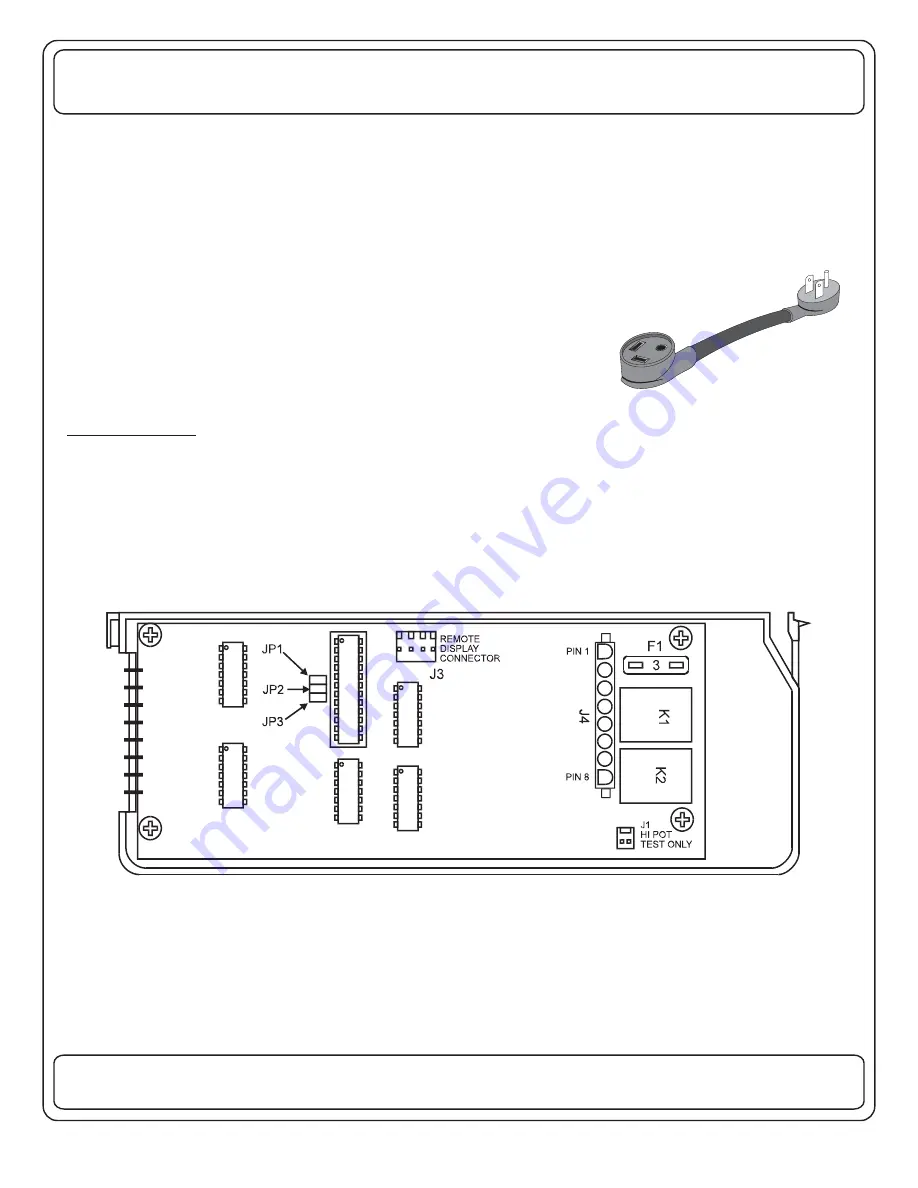
The EMS has three jumpers on the board that determine the order of shedding of the loads. These jumpers are labeled
JP1, JP2, and JP3. (See figure below.)
These jumpers are all installed at the factory. Removing them will alter the order of shedding to suit the particular need of
the installation. The following tables will assist in determining the proper settings for the three jumpers.
The first step is to fill in the blanks with the names of the loads you want the system to shed, in the order they are to be shed,
with the first to be shed at the top. Then, fill in the second, "Load Type", column with an "A" or a "D", an "A" for a 120 VAC
controlled load such as a washer/dryer, or a "D" for DC controlled load, such as a thermostat wire. You can select a
maximum of 3 AC\1 DC relays, or 2 AC\2 DC relays.
INSTALLATION


