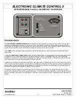


ELECTRONIC CLIMATE CONTROL II
SERVICE MANUAL Part No’s. 00-00855-000 / 00-00856-000
Intellitec
1485 Jacobs Rd.
Deland, FL 32724
386.738.7307
www.Intellitec.com
- 3 -
P/N 53-00855-856 Rev. C 080819
LOW COOL -
The air conditioner fans are energized on low speed. The compressor for A/C 1 turns on when the
ambient temperature at the front temperature probe exceeds the set temperature, and stays on until that
temperature is reduced below the set temperature. Compressor for A/C 2 turns on when ambient
temperature at the front temperature probe exceeds 1 degree above set temperature, and stays on until
that temperature is reduced below 1 degree above set temperature. Load shedding is active.
.
HIGH COOL -
The air conditioner fans are energized on high speed. The compressor for A/C 1 turns on when the
ambient temperature at the front temperature probe exceeds the set temperature, and stays on until that
temperature is reduced below the set temperature. Compressor for A/C 2 turns on when the ambient
temperature at the front temperature probe exceeds 1 degree above set temperature, and stays on until
that temperature is reduced below 1 degree above set temperature. Load shedding is active.
AUTO COOL -
As difference between the ambient temperature at the front temperature probe and the set-point
temperature increases, A/C functions will turn on in the following order: (Diff. Temp = Ambient
Temperature at the front temperature probe - Set-Point Temp, i.e. 2F means Room Temp is 2
degrees
Fahrenheit higher than Set Temp).
Diff. Temp
A/C 1 Function
A/C 2 Function
0°F to +1°F
Fan
Low & Compressor
Fan
Low
+1°F to +2°F Fan
High
& Compressor
Fan
High
& Compressor
Once an A/C compressor turns on, the room will have to cool by 1 degree F, in order for the A/C compressor to turn back
off (1
degree F hysteresis). Both the air conditioner compressor and high fan are on when the ambient temperature goes
2 degrees above the set point temperature. When the ambient temperature drops to within 1 degree of the set point the
fan switches to low speed. When the temperature drops to the set point, the compressor turns off. When the temperature
drops 2 degrees below set point the fans will shut off. As the ambient temperature rises, the reverse procedure happens.
Load shedding is active.
INDICATOR LIGHTS:
There are two indicator lights on the control panel for each of the front (A/C1) and (A/C2) systems. The green
ON
indicator will be lit when the associated function switch is in
any
cooling mode. The red
SHED
indicator will be lit
when the system calls for the associated air conditioner compressor to start. The red
SHED
indicators will blink
when the system is holding off operation of the air conditioner compressor during the 2 minute
”
short-cycle”
protection cycle (
see ECC Control Module
).
THE ECC TEMPERATURE PROBES:
The temperature probes are thermistors mounted in protective plastic housings so they can sense the temperature of the
air without being influenced by the mounting surface temperature. Thermistors vary their electrical resistance
inversely
with temperature: the higher the temperature, the lower the resistance. The thermistors utilized in
this system have a resistance of about 10,000 Ohms at 77 degrees.
There are two temperature probes; one for the front of the coach which controls all A/C functions,
front furnace and one for the rear which only controls the rear furnace (when so equipped). They
are located remotely from the thermostat panel to sense temperatures in the front and rear. The
temperature connections to the ECC Thermostat are via small 2 pin connectors labeled J1 (FRONT) and J4 (REAR).
Since the devices are not polarity sensitive, the two wires leading to them can be reversed without harm. However, it is
necessary to connect the front and rear temperature probes to the correct connector to ensure the ECC Thermostat
interprets the correct ambient temperatures associated with the front and rear of the coach.