IntelliSAW IRM-48 Reader
Installation Manual
Page 17 of 28
IRM-48 Reader
910.00371.0001
IMPORTANT
There are two INDEPENDENT connections that shall be individually wired to the
Protective Earth of the installation site such that there is an extremely low impedance
between the enclosures; this is best achieved using the shortest possible ground
cable.
4.2
C
OMMUNICATION
C
ONNECTIONS
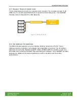
The IntelliSAW readers are connected in a network using a standard, half-duplex RS485 bus.
This is a 3-wire bus, differential signals for data +/- and a common signal return. The common
signal is clamped to PE for safety and connects to the line driver through a high resistance to
prevent ground loops. The figure below shows the various elements of a network in a
switchgear substation.
Figure 11: RS485 Data Communication Bus Topology
4.2.1.1 Recommended Cabling
IntelliSAW recommends the use of shielded cable for the RS485 wiring, providing at least one
twisted pair, one single line, and a drain wire, although typical cable has two twisted pair. The
twisted pair provides DATA+/- signals to each reader while the single line would be for D-COM,
providing a low-impedance return for each reader.
4.2.1.2 Bus cable shielding
The drain wire associated with the RS485 bus shielding foil should be connected to the
protective earth at the source end (the end of the line segment closest to the bus master) with
the destination end left unconnected. This prevents ground loops and induced noise. Each


