background image

-13-

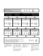
Input the master code.
(Default:   [                  ]+[#] )

   23.Delete user card

   24.Format user card

   22.Add user card

Input the setting code. 

Input the setting code. 

   21.Register [Manage card]

100+#

101+#

102+#

103+#

Inputting of code

1234+#

Inputting of code

1234+#

Inputting of code

1234+#

Inputting of code

1234+#

Input the setting code.

Input the setting code.

- Swipe the first card to ID card 

window, it will be set to 

MASTER 

CARD ADD

 card.

- Swipe the second card to ID card

window, it will be set to 

MASTER 

CARD DELETE

 card.

-When registered new master 

cards, the old master cards are

invalid automatically.

- Another way:

Swipe the 

MASTER CARD ADD


card to ID card window in standby 

mode, and then swipe user cards 

one by one to be added.

- Another way:

Swipe the 

MASTER CARD DELETE


card to ID card window in standby 

mode, and then swipe user cards 

one by one to be deleted.

Beep+, Beep

(on)

(off)

(off)

LED1

LED2

LED3

Beep+, Beep

(flash)

(off)

(off)

LED1 LED2 LED3

Beep+, Beep

(flash)

(off)

(off)

LED1 LED2 LED3

Beep+

(off)

(on)

(off)

LED1 LED2 LED3

Beep+

(off)

(on)

(off)

LED1 LED2 LED3

Beep+, Beep

(flash)

(off)

(off)

LED1 LED2 LED3

Beep+

(off)

(flash)

(off)

LED1 LED2 LED3

Beep+, Beep

(flash)

(off)

(off)

LED1 LED2 LED3

Beep+

(off)

(off)

(off)

LED1 LED2 LED3

Swipe 

MASTER CARD ADD

 card

and 

MASTER CARD DELETE


card in the ID window.

Swipe new user card one by one
to be added in the ID window.

Swipe user card one by one to be
deleted in the ID window.

Beep+

(off)

(flash)

(off)

LED1 LED2 LED3

Beep+

(off)

(on)

(off)

LED1 LED2 LED3

Beep+

(off)

(flash)

(off)

LED1 LED2 LED3

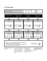
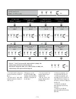
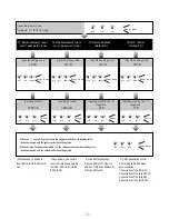
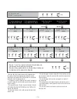
When the  “     cancel”  key is pressed, the  indicator will show its standby color,  
the buzzer beeps, and the system exits the setting mode.

When there isn’t any operation within 10s, the  indicator will show its standby color,  

   the buzzer beeps, and the system exits the setting mode.

Beep, Beep+

 *

(off)

(off)

(off)

LED1 LED2 LED3

Summary of Contents for DT-AKP

Page 1: ...ual RF CARD DT ENG AKP V1 201701 Please read this manual carefully to ensure safe and correct operation Keep this manual well for future reference DT AKP 2 WIRE SYSTEM Access keypad panel with scrambl...

Page 2: ...ad 3 LED1 indicator 4 LED2 indicator 5 LED3 indicator 6 ID card window 7 Mounting hook 8 Connection port 9 Screw hole SD Card Slot To insert micro SD card BUS Connect to the bus line non polarity 12V...

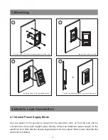
Page 3: ...ect the cable correctly 4 Electric Lock Connection 4 1 Internal Power Supply Mode Use the power of the system to supply for the electronic lock so that the lock can be connected to the access keypad p...

Page 4: ...wer on to Unlock type 12V 300mA 12V LK GND LK COM N O EB EB Set Unlock Relay mode to Normally Closed 1 B Connection for Power off to Unlock type 4 2 External Power Supply Mode When the electronic lock...

Page 5: ...o continue the setting operation Press to exit the setting mode The example is set as cancel button and as confirm button please refer to function setting for detail information Forbid sliding touch t...

Page 6: ...12 Unlock work mode 11 Valid keys 0 3 0 13 Backup master user card password tone 12 1 2 3 4 14 Update master user card password tone 13 1 2 3 4 15 Device Address 14 Valid keys 0 3 0 16 RLC Control 15...

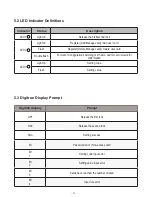
Page 7: ...elete user card Double flash Format or Configuration switching of DT ACC and ID card it waits for confirmation LED3 Light on Setting code Flash Setting value Digitron display Prompt OP1 Release the fi...

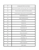
Page 8: ...application ID The access control is configured for the ID card unlock application S A Register Add Manage card S D Register Delete Manage card ADD Add user card DEL Delete user card CLE Format user...

Page 9: ...ut the setting code Inputting of code Input the setting code 1 Reset all settings 00 1234 4321 01 0 09 Input the setting code 02 Input the setting code 03 Digitron display mode 0 The scrolling display...

Page 10: ...the item is set to 1 press the button to cancel the input and press the button to confirm the input on off off LED1 LED2 LED3 Beep Beep flash off off LED1 LED2 LED3 Beep Beep flash off off LED1 LED2...

Page 11: ...setting code 11 Inputting of value ex 0 range 0 3 0 Default 0 0 Unlock via password or user card only release the first lock 1 Unlock via password or user card swipe user card once time to release th...

Page 12: ...address auto correlation 1 Association of the first RLC 2 Association of the second RLC 3 Association of the third RLC 4 Association of the fourth RLC Beep Beep on off off LED1 LED2 LED3 Beep Beep fl...

Page 13: ...re will be cleared at the same time The temporary code can not be set the same as the master code and user code The user code group1 is used to release the first lock and the user code group2 is used...

Page 14: ...nd then swipe user cards one by one to be deleted Beep Beep on off off LED1 LED2 LED3 Beep Beep flash off off LED1 LED2 LED3 Beep Beep flash off off LED1 LED2 LED3 Beep off on off LED1 LED2 LED3 Beep...

Page 15: ...one Select item is set to 1 then the electric door strike is unlocked The time interval between 2 digitals input must be less than approximately 10 seconds otherwise the input value will be cleared If...

Page 16: ...n access control keypad directly Excessive moisture may cause problems with the unit You must use the right adaptor which is supplied by the manufacture or approved by the manufacture Pay attention to...

Reviews: