Thermal/Mechanical Design Guide
27
LGA1366 Socket and ILM Electrical, Mechanical, and Environmental Specifications
4
LGA1366 Socket and ILM
Electrical, Mechanical, and
Environmental Specifications
This chapter describes the electrical, mechanical, and environmental specifications for
the LGA1366 socket and the Independent Loading Mechanism.
4.1
Component Mass
4.2
Package/Socket Stackup Height
Table 4-2
provides the stackup height of a processor in the 1366-land LGA package and
LGA1366 socket with the ILM closed and the processor fully seated in the socket.
Notes:
1.
This data is provided for information only, and should be derived from: (a) the height of the socket seating
plane above the motherboard after reflow, given in
Appendix C
, (b) the height of the package, from the
package seating plane to the top of the IHS, and accounting for its nominal variation and tolerances that
are given in the corresponding processor EMTS.
2.
This value is a RSS calculation.
4.3
Socket Maximum Temperature
The power dissipated within the socket is a function of the current at the pin level and
the effective pin resistance. To ensure socket long term reliability, Intel defines socket
maximum temperature using a via on the underside of the motherboard. Exceeding the
temperature guidance may result in socket body deformation, or increases in thermal
and electrical resistance which can cause a thermal runaway and eventual electrical
failure. The guidance for socket maximum temperature is listed below:
• Via temperature under socket < 96 °C
Table 4-1.
Socket Component Mass
Component
Mass
Socket Body, Contacts and PnP Cover
15 gm
ILM Cover
43 gm
ILM Back Plate for dual processor server products
100 gm
Table 4-2.
1366-land Package and LGA1366 Socket Stackup Height
Integrated Stackup Height (mm)
From Top of Board to Top of IHS
7.729 ± 0.282 mm
Summary of Contents for X5550 - Quad Core Xeon
Page 8: ...8 Thermal Mechanical Design Guide ...
Page 12: ...Introduction 12 Thermal Mechanical Design Guide ...
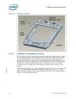
Page 24: ...Independent Loading Mechanism ILM 24 Thermal Mechanical Design Guide Figure 3 3 ILM Assembly ...
Page 26: ...Independent Loading Mechanism ILM 26 Thermal Mechanical Design Guide ...
Page 48: ...Component Suppliers 48 Thermal Mechanical Design Guide ...
Page 82: ...Mechanical Drawings 82 Thermal Mechanical Design Guide ...
Page 88: ...Socket Mechanical Drawings 88 Thermal Mechanical Design Guide ...


