Intel SRCSASLS4I - RAID Controller Hardware User'S Manual Download Page 25

Intel® RAID Controller SRCSASLS4I Hardware User’s Guide

19

English

Read all caution and safety statements in this document before performing any of the 
instructions. See also Intel Server Boards and Server Chassis Safety Information on the 
Resource CD and/or at http:\\support.intel.com\support\motherboards\server\sb\cs-
010770.htm.

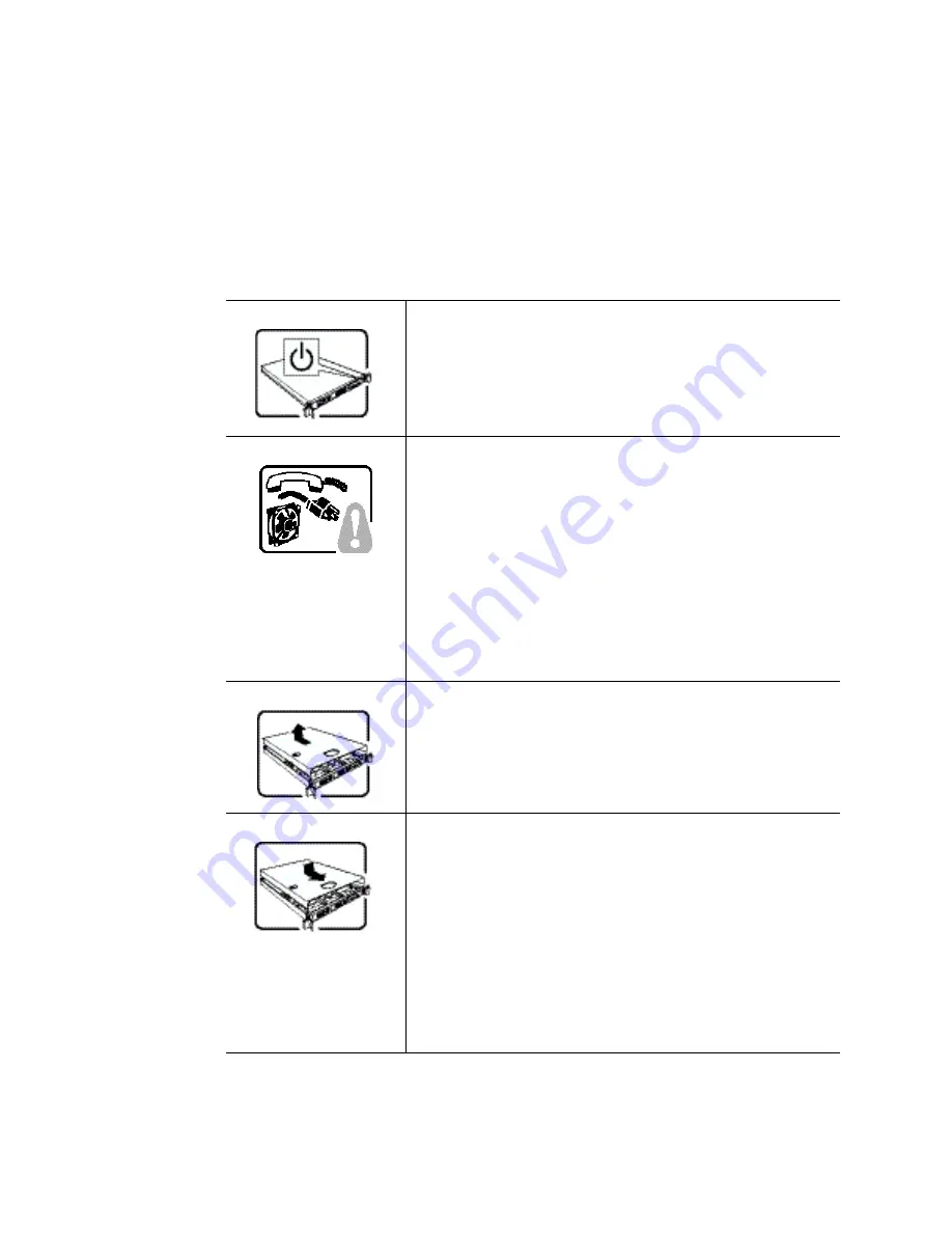
The power button on the system does not turn off system AC power. 

To remove AC power from the system, you must unplug each AC 

power cord from the wall outlet or power supply.

The power cord(s) is considered the disconnect device to the main 

(AC) power. The socket outlet that the system plugs into shall be 

installed near the equipment and shall be easily accessible.

SAFETY STEPS:

 Whenever you remove the chassis covers to 

access the inside of the system, follow these steps:

1. Turn off all peripheral devices connected to the system.
2. Turn off the system by pressing the power button.
3. Unplug all AC power cords from the system or from wall 

outlets.

4. Label and disconnect all cables connected to I/O connectors 

or ports on the back of the system.

5. Provide some electrostatic discharge (ESD) protection by 

wearing an antistatic wrist strap attached to chassis ground of 

the system-any unpainted metal surface-when handling 

components.

6. Do not operate the system with the chassis covers removed.

After you have completed the six SAFETY steps above, you can 

remove the system covers. To do this:

1. Unlock and remove the padlock from the back of the system if 

a padlock has been installed.

2. Remove and save all screws from the covers.
3. Remove the cover(s).

For proper cooling and airflow, always reinstall the chassis covers 

before turning on the system. Operating the system without the 

covers in place can damage system parts. To install the covers:

1. Check first to make sure you have not left loose tools or parts 

inside the system.

2. Check that cables, add-in cards, and other components are 

properly installed.

3. Attach the covers to the chassis with the screws removed 

earlier, and tighten them firmly.

4. Insert and lock the padlock to the system to prevent 

unauthorized access inside the system.

5. Connect all external cables and the AC power cord(s) to the 

system.


Summary of Contents for SRCSASLS4I - RAID Controller

Page 1: ...Intel RAID Controller SRCSASLS4I Hardware User s Guide Intel Order Number E33167 002...

Page 2: ...S INCLUDING LIABILITY OR WARRANTIES RELATING TO FITNESS FOR A PARTICULAR PURPOSE MERCHANTABILITY OR INFRINGEMENT OF ANY PATENT COPYRIGHT OR OTHER INTELLECTUAL PROPERTY RIGHT Intel products are not int...

Page 3: ...nefit from this book are Engineers who are designing an Intel RAID Controller SRCSASLS4I storage adapter into a system Anyone installing an Intel RAID Controller SRCSASLS4I storage adapter in their RA...

Page 4: ...iv Intel RAID Controller SRCSASLS4I Hardware User s Guide...

Page 5: ...lation 7 Requirements 7 Install the RAID Controller 7 Configure the RAID Controller 10 Replacing a Controller Resolving a Config Mismatch 10 Chapter 3 Intel RAID Controller SRCSASLS4I Characteristics...

Page 6: ...vi Intel RAID Controller SRCSASLS4I Hardware User s Guide...

Page 7: ...for the RAID controller even during system failures Benefits of SAS SAS is a serial point to point enterprise level device interface that leverages the proven SCSI protocol set SAS is a convergence o...

Page 8: ...her SATA II devices Serial Management Protocol SMP Topology management information sharing with expanders Serial Tunneling Protocol STP support for SATAII through expander interfaces Operating System...

Page 9: ...ES2 Enclosure management support Fault indicators per drive Drive coercion auto resizing to match existing disks Auto detection of failed drives with transparent rebuild There must be disk activity I...

Page 10: ...ta is not in the cache Direct I O Reads data directly from disk not cache Redundancy through Configuration stored in nonvolatile RAM and on the drives COD Hot swap support Optional battery backup for...

Page 11: ...5 to RAID 0 RAID 6 to RAID 0 With OCE migrations supported are RAID 0 to RAID 1 RAID 0 to RAID 5 RAID 1 to RAID 5 Beep Codes Short beep 1 second on 1 second off Array is degraded but no data lost Lon...

Page 12: ...6 Intel RAID Controller SRCSASLS4I Hardware User s Guide...

Page 13: ...tion SAS or SATA 3 0 hard drives Note Intel Corporation strongly recommends using an uninterruptible power supply UPS Install the RAID Controller 1 Turn off the power to the system and all drives encl...

Page 14: ...ler SRCSASLS4I 5 For the four drives ports 0 3 connect one 4 port combined end of an internal cable to the connector See the following figure To prevent throughput problems use the cable provided or u...

Page 15: ...LS4I Hardware User s Guide 9 Figure 3 Connecting Cable between the RAID Controller and Drives Backplane 6 Install the server system cover and connect the power cords See your server system documentati...

Page 16: ...e server board 3 See the Quick Start User s Guide and the Software User s Guide for instructions to configure the RAID controller and to install the operating system drivers Replacing a Controller Res...

Page 17: ...n to disk J3 Drive Activity LED Header 2 pin connector LED signal for drive activity J4 Debug Connector 2 pin connector Reserved J5 Universal Asynchronous Receiver Transmitter UART 4 pin connector For...

Page 18: ...2 5 Gbps SATA bus speed 3 Gbps per port point to point Serial port 3 pin RS232 compatible connector for debug use only SAS controller LSI 1078 SAS SATA ports 1x4 internal port up to 4 direct attached...

Page 19: ...ion OCE and Patrol Read Cache options Write back or Write through Read Ahead Adaptive Read Ahead NonRead Ahead Cache I O or Direct I O Self Monitoring Analysis and Reporting Technology SMART support D...

Page 20: ...oard is marked with the supplier name or trademark type and UL flammability rating For the boards installed in a PCI bus slot all voltages are lower than the SELV 42 4 V limit PCI 12 V PCI 3 3 Aux PCI...

Page 21: ...use drive roaming 1 Turn off the power to the system and all drives enclosures and system components Remove the power cord s 2 Follow the instructions that came with your server system to remove the s...

Page 22: ...tem and all drives enclosures and system components Remove the power cord s 3 Follow the instructions that came with your server system to remove the server cover 4 Disconnect the cables from the driv...

Page 23: ...protect your computer system from sudden transient increases and decreases in electrical power use a surge suppressor line conditioner or uninterruptible power supply Be sure nothing rests on your com...

Page 24: ...nt static damage discharge static electricity from your body before you touch any of your computer s electronic components such as the microprocessor You can do so by touching an unpainted metal surfa...

Page 25: ...onnect all cables connected to I O connectors or ports on the back of the system 5 Provide some electrostatic discharge ESD protection by wearing an antistatic wrist strap attached to chassis ground o...

Page 26: ...alter f r Gleichstrom nicht ausgeschaltet Ziehen Sie jedes Wechselstrom Netzkabel aus der Steckdose bzw dem Netzger t um den Stromanschlu des Systems zu unterbrechen SICHERHEISMASSNAHMEN Immer wenn Si...

Page 27: ...dem Einschalten installiert werden Ein Betrieb des Systems ohne angebrachte Abdeckung kann Ihrem System oder Teile darin besch digen Um die Abdeckung wieder anzubringen 1 Vergewissern Sie sich da Sie...

Page 28: ...reliez la la masse du syst me toute surface m tallique non peinte du bo tier 6 Ne faites pas fonctionner le syst me tandis que le bo tier est ouvert Une fois TOUTES les tapes pr c dentes accomplies vo...

Page 29: ...erruptor activado desactivado en el panel frontal no desconecta la corriente alterna del sistema Para desconectarla deber desenchufar todos los cables de corriente alterna de la pared o desconectar la...

Page 30: ...mpruebe que los cables las placas adicionales y otros componentes se hayan instalado correctamente 3 Incorpore las tapas al chasis mediante los tornillos extra dos anteriormente tens ndolos firmemente...

Page 31: ...del sistema qualora ve ne fosse uno installato 2 Togliere e mettere in un posto sicuro tutte le viti delle coperture 3 Togliere le coperture Per il giusto flusso dell aria e raffreddamento del sistema...

Page 32: ...26 Intel RAID Controller SRCSASLS4I Hardware User s Guide...

Page 33: ...iance Class B FCC ICES 003 USA Canada CISPR 22 International EN55022 Europe EN55024 Europe CE EMC Directive 89 336 EEC Europe VCCI Japan AS NZS 3548 Australia New Zealand BSMI CNS13438 Taiwan RRL MIC...

Page 34: ...the FCC Rules Operation of this device is subject to the following two conditions 1 This device may not cause harmful interference and 2 This device must accept any interference received including int...

Page 35: ...ide reasonable protection against harmful interference in a residential installation This equipment generates uses and can radiate radio frequency energy and if not installed and used in accordance wi...

Page 36: ...tal apparatus set out in the interference causing equipment standard entitled Digital Apparatus ICES 003 of the Canadian Department of Communications Cet appareil num rique respecte les limites bruits...

Reviews: