background image

1

System Overview

Intel® Server System R2000BB Family

Useful Information:

• The system must be configured with two CPUs to enable PCIe slot 1 (Top) 

and

 PCIe slot 2 (middle) on Riser #2.

• The mini-SAS connector labeled SCU_1 requires an 8-port SATA/SAS Intel

®

 RAID C600 Upgrade Key to be functional.

• DIMM channels D-F can only be used in dual processor configurations.
• The CPU-2 heat sink must be installed with or without a processor installed.

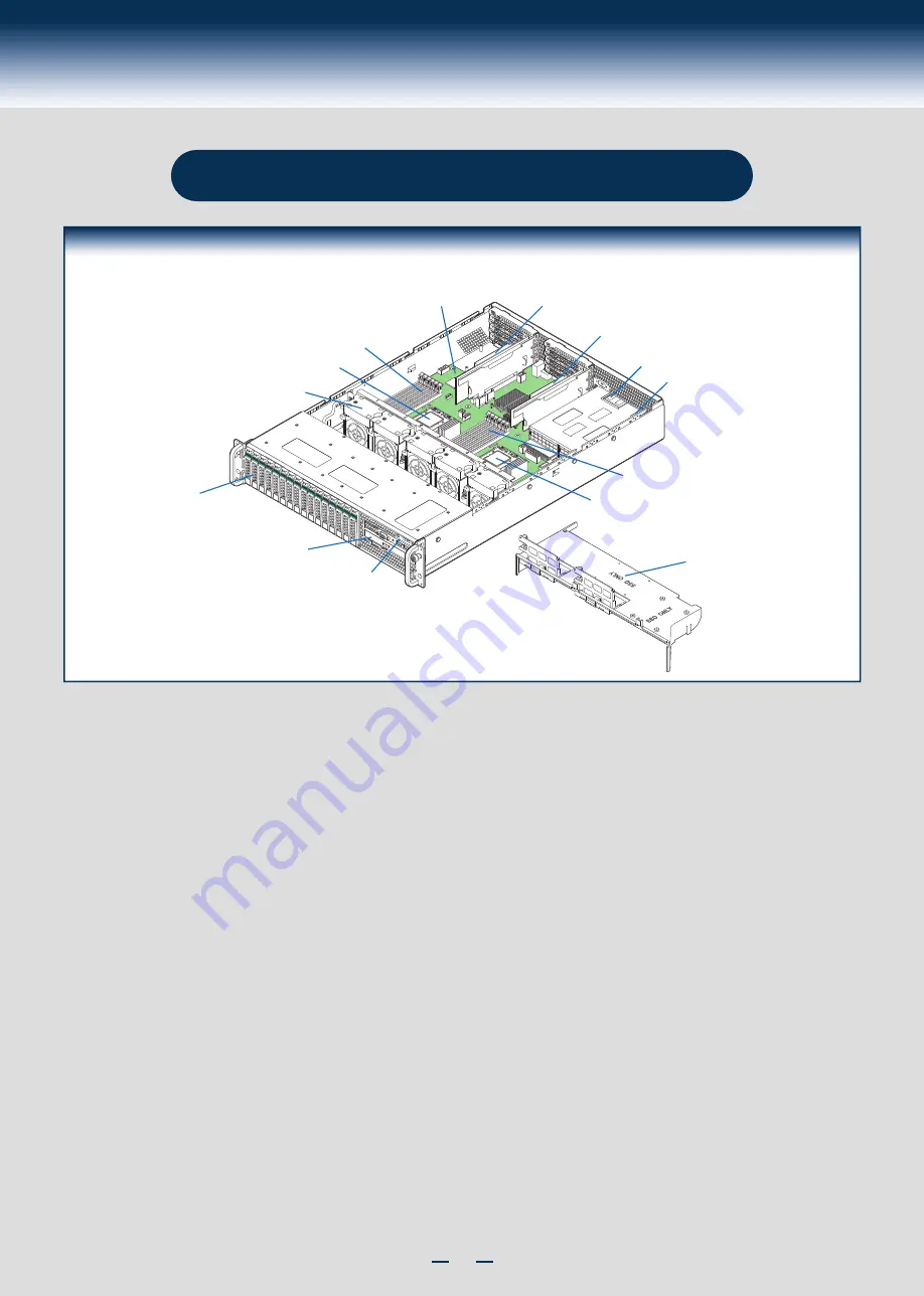
System Features and Components

Hot Swap

Hard Drive Bays

System Fans

CPU2

CPU2

Memory Slots

CPU1

Memory Slots

CPU1

PCI Riser #2

Power Supply

#1

Server Board

Air Duct

Optical Drive Bay

Front Control Panel

PCI Riser #1

Power Supply

#2

* 2.5" Hard Drive Bay system as shown

Summary of Contents for R2000BB series

Page 1: ...familiar with ESD Electrostatic Discharge procedures used during system integration see the complete ESD procedures described in your Service Guide This guide and other supporting documents are locate...

Page 2: ...This page is intentionally left blank...

Page 3: ...5 Install Optical Drive 7 Install the Air Duct 7 Remove Add in Card Riser Assembly 7 Install Add in Card s 7 Install Add in Card Riser Assembly 8 Install Rack Handles 8 Install Intel I O Expansion Mo...

Page 4: ...stem must meet the following operating and configuration guidelines Ambient in let temperature cannot exceed 35 C and should not remain at this maximum level for long periods of time Doing so may affe...

Page 5: ...RAID C600 Upgrade Key to be functional DIMM channels D F can only be used in dual processor con gurations The CPU 2 heat sink must be installed with or without a processor installed System Features a...

Page 6: ...NT Before proceeding further check your Intel Server System for disconnected or loose cables and components that may have occurred during shipping B A 3 Remove the Air Duct Carefully push in the two l...

Page 7: ...rotective cover C D Orientation Posts Orientation Notches A Install the Processor s continued E Close Load Plate and Socket Lever Close the socket lever and ensure that the load plate tab engages unde...

Page 8: ...assis Each heatsink has four captive fasteners and should be tightened in a diagonal manner using the following procedure Using a 2 Phillips screwdriver start with screw 1 and engage screw threads by...

Page 9: ...mbering Diagram Drive 0 Primary 24 x 2 5 hard drive bay as shown A A B Press the green latch to unlock Pull out the black lever and slide the carrier out B D C Remove the four screws securing the plas...

Page 10: ...hown Slide the 2 5 HDD into the plastic drive blank to align the screw holes with the right and left rail Break off the tab on the plastic drive blank Install 2 5 Hard Drive as option Secure the hard...

Page 11: ...wo tabs on the fan bulkhead A Carefully push in the two latches on the air duct B Push down the air duct into place C Riser Card Connector 11 Remove Add in Card Riser Assembly Grasp the riser assembly...

Page 12: ...e blue plastic pin into the card guide to secure the add in card NOTE Step A B D and E are only needed when a full length PCI card is installed on the riser assembly Riser Slot 2 is not functional wit...

Page 13: ...ack Opening Filler A B C Finger Hole A B 19 Install Second Power Supply Module optional A B Use the finger hole to remove the filler panel Insert the power supply module into the power supply cage and...

Page 14: ...rivers to install On other operating systems browse the DVD folders to locate and install the driver files Download the latest version of the Intel System Management Software from http www intel com g...

Page 15: ...cket HSBP Power Front Panel USB Front Panel Video CPU 1 Socket USB Serial A RMM4 Lite USB Type A SCU_0 SCU_1 Video NIC4 NIC3 Status LED NIC2 NIC1 Diagnostic LEDs mSATA SSD LP eUSB SSD Chassis Intrusio...

Page 16: ...te list of accessories and spares can be found at http www intel com support Air Flow CPU2 Socket CPU1 Socket FAN 1 FAN 5 FAN 2 FAN 3 FAN 4 System Fan Connection NOTE System FAN connector 5 on the ser...

Page 17: ...B PCIe RAID Install into PCIe Riser Card 0 1 B B U Optical Drive SSD Mount on air duct FAN 1 FAN 2 FAN 3 FAN 4 FAN 5 System Cabling Diagram NOTE To activate the port SCU1 4 7 on the server board a pro...

Page 18: ...4 5 0 1 I 2 C Front Panel Interposer Board PCIe RAID 0 1 Mount on air duct Install into PCIe Riser Card B B U FAN 1 FAN 2 FAN 3 FAN 4 FAN 5 System Cabling Diagram For system with 12 x 3 5 hard drive b...

Page 19: ...B PCIe RAID Install into PCIe Riser Card 0 1 B B U Optical Drive FAN 1 FAN 2 FAN 3 FAN 4 FAN 5 SSD Mount on air duct System Cabling Diagram For system with 8 x 2 5 hard drive bay NOTE To activate the...

Page 20: ...el Video Front Panel USB PCIe RAID Install into PCIe Riser Card 0 1 B B U Optical Drive FAN 1 FAN 2 FAN 3 FAN 4 FAN 5 SSD Mount on air duct System Cabling Diagram For system with 16 x 2 5 hard drive b...

Page 21: ...rd SSD I 2 C I 2 C I 2 C PCIe RAID Install into PCIe Riser Card 0 1 8 x 2 5 HSBP Mount on air duct B B U FAN 1 FAN 2 FAN 3 FAN 4 FAN 5 System Cabling Diagram For system with 24 x 2 5 hard drive bay NO...

Page 22: ...G48801 002...

Reviews: