11
Reference
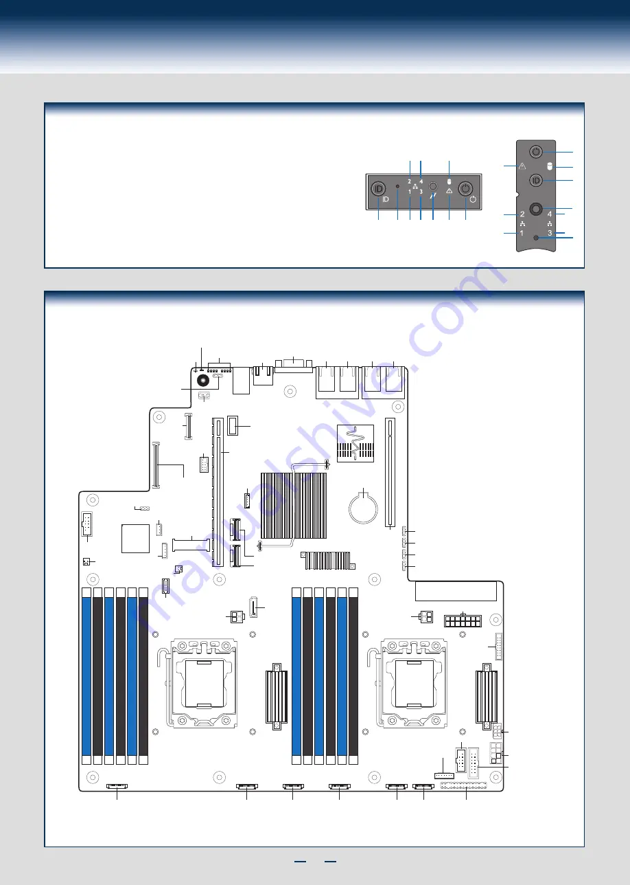
Front Panel Controls and Indicators
Standard Control Panel
H
I
J
A
B C D E F G
Your system may include one of two front control panel types.The
features of each are as follows:
A. ID Button with integrated LED
B. NMI Button (recessed, tool required)
C. LAN-1 Activity LED
D. LAN-3 Activity LED
E. System Cold Reset Button
F. System Status LED
G. Power Button with integrated LED
H. HDD Activity LED
I. LAN-4 Activity LED
J. LAN-2 Activity LED
G
H
A
E
I
D B
F
J
C
Integrated
BMC
ID LED
Serial Jumper
RMM4
NIC
Riser Slot_2
Riser Slot_1
I/O Expansion
Module
Connector
Serial B
TPM Connector
CPU 2 Socket
HSBP Power
Front Panel USB
Front Panel Video
CPU 1 Socket
USB
Serial A
RMM4 Lite
USB Type A
SCU_0
SCU_1
Video
NIC4 NIC3
Status
LED
NIC2 NIC1
Diagnostic
LEDs
mSATA SSD
LP eUSB SSD
Chassis Intrusion
HDD LED
SATA 1
Optional
12V Power 2
Optional
12V Power 1
PDB
Control
PDB Power
LCP
ODD/SSD Power
System
Fan 1
System
Fan 2
System
Fan 3
System
Fan 4
System
Fan 5
System
Fan 6
Front Panel
DIMM_D1
DIMM_D2
DIMM_E1
DIMM_E2
DIMM_F1
DIMM_F2
DIMM_A1
DIMM_A2
DIMM_B1
DIMM_B2
DIMM_C1
DIMM_C2
HSBP_I
2
C
BMC Force
Update Jumper
IPMB
Battery
Main Power 1
Storage
Upgrade
Key
BIOS Recovery Jumper
ME Force Update Jumper
Password Clear Jumper
BIOS Default Jumper
Intel® Server Board R2000BB Component Layout
See your
Intel
®
Server System R2000BB Service Guide
for expanded component and connection information.
Summary of Contents for R2000BB series
Page 2: ...This page is intentionally left blank...
Page 22: ...G48801 002...


