background image


19


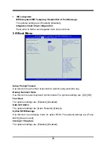
System Language 

Choose the system default language. The optional settings are: [English]; [Chinese]. 

System Date 

Set the date. Please use TAB to switch between data elements. 

System Time 

Set the date. Please use TAB to switch between time elements. 

3-7 Advanced Menu 


Summary of Contents for P67

Page 1: ...ssors Trademark Specifications and Information contained in this documentation are furnished for information use only and are subject to change at any time without notice and should not be construed a...

Page 2: ...i Environmental Protection Announcement Do not dispose this electronic device into the trash while discarding To minimize pollution and ensure environment protection of mother earth please recycle...

Page 3: ...EDURE FOR EXPANSION CARD INSTALLATION 9 2 5 3 INSTALLING CROSSFIRE SLI CARD BRIDGE 10 2 6 CONNECTORS AND HEADERS 11 2 6 1 I O BACK PANEL CONNECTORS 12 2 6 2 INTERNAL CONNECTORS 14 2 6 3 INTERNAL HEADE...

Page 4: ...it is moved from a cold environment to a warmer one to avoid condensation phenomenon These water drops attached on PCB or the surface of the components can bring about phenomena as minor as computer i...

Page 5: ...Revision Information Reversion Revision History Date 1 0 First Edition December 2010 Item Checklist 5 Intel P67 Express chipset based motherboard 5 User s manual 5 DVD for motherboard utilities 5 Cabl...

Page 6: ...2 bit PCI slot SATA2 SATA3 z Supports four internal Serial ATAII ports providing 3 0 Gb sec data transfer rate and two SATAIII devices providing 6 0 Gb sec data transfer rate z Support RAID 0 1 5 10 G...

Page 7: ...125 degrees centigrade OC CON capacitors possess superior physical characteristics to prolong product life ten times than corresponding motherboard without capacitors every time working temperature in...

Page 8: ...axial SPDIF_OUT PCI Express 2 0 x16 by 16 Lane Reset Button JBAT Gigabit LAN Chip 8 CH HD Audio Connector POWER CAP USB 2 0 Ports USB 3 0 Port PS 2 Keyboard Port Intel P67 Chipset 64MB Flash ROM 8 CH...

Page 9: ...ault 8 Reboot 9 Install Operating System 10 Install Driver and Utility 2 2 Checking Motherboard s Jumper Setting 1 CMOS RAM Clear 3 pin JBAT A battery must be used to retain the motherboard configurat...

Page 10: ...t sink and CPU cooling FAN is working correctly otherwise it may cause the processor and motherboard overheat and damage you may install an auxiliary cooling FAN if necessary To install a CPU first tu...

Page 11: ...al protection plate will be pulled up at the same time 4 Remove the plastic protective cap from the socket Put it to the original place if CPU is not installed Do not touch the metal contact point of...

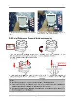
Page 12: ...unter clockwise direction 3 Press down two fasteners down in the oblique crossing direction as shown above 4 Turn over the motherboard carefully to make sure the fastener insert in the right direction...

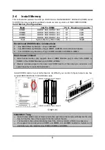
Page 13: ...DIMM Modules plug in either both DIMM1 DIMM3 or four DIMM Modules plug in DIMM1 DIMM4 2 Memory modules plugged in the same color DIMM must be of the same type same size and same frequency for dual ch...

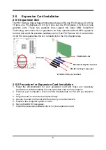
Page 14: ...antee the rich connectivity for the I O of peripherals 2 5 2 Procedure for Expansion Card Installation 1 Read the documentation for your expansion card and make any necessary hardware or software sett...

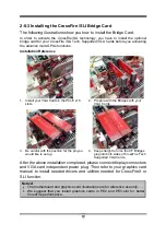
Page 15: ...he Bridges with your VGA Cards 3 Be careful with the position for the pin you would like to set up 4 Keep straight to force the CF Bridges plug into both sides of CrossFire Tech Supported VGA Cards Af...

Page 16: ...board Mouse Connectors from USB20_KB_MS The connector is provided to connect PS 2 keyboard input devices 6 LAN Port connector RJ 45 LAN port from USB20_LAN This connector is standard RJ 45 LAN jack fo...

Page 17: ...s If you intend to use a PSU with 20 pin and 4 pin power plugs make sure that the 20 pin power plug can provide at least 15A on 12V and the power supply unit has a minimum power rating of 350W The sys...

Page 18: ...provide sufficient current for system Pin 1 3 Serial ATA3 Port connectors SATA1 SATA2 These SATAIII connectors support SATA 6Gb s specification Please connect SATAIII device to the connector with SATA...

Page 19: ...Please connect it to CD ROM CD Audio output connector CD Audio In Header Pin 1 L GND R 3 SPDIF Out header HDMI_SPDIF1 This header provides S PDIF digital signal transmission Please connect it to cert...

Page 20: ...er ON OFF the system System Case Connections HDLED RESET VCC5 GND VCC5 PWR LED PWRBTN PWRBTN PWRLED HDDLE RSTSW NC GND JW FP Pin 1 SPEAK SPKR GND NC VCC5 Pin 1 PWRLED Pin 1 9 USB 2 0 Port Headers 9 pi...

Page 21: ...on the fan manufacturer the wire and plug may be different The red wire should be positive while the black should be ground Please connect the fan s plug to the board taking into consideration the pol...

Page 22: ...mmunicate it is the key factor for system stability and in ensuring that your system performance as its best 3 1 Entering Setup Power on the computer and by pressing Del immediately allows you to ente...

Page 23: ...setup function is displayed at the top right corner the screen Status Page Setup Menu Option Page Setup Menu Press F1 to pop up a small help window that describes the appropriate keys to use and the...

Page 24: ...system default language The optional settings are English Chinese System Date Set the date Please use TAB to switch between data elements System Time Set the date Please use TAB to switch between tim...

Page 25: ...ke up by Ring CPU Configurations Active Processor Cores Use this item to select number of cores to enable in each processor package Limit CPUIP Maximum This item should be set as Disabled for Windows...

Page 26: ...mode 1 Core Ratio Limit 2 Core Ratio Limit 3 Core Ratio Limit 4 Core Ratio Limit Use these items to set core ratio limit for respective core The optional setting range is from 0 to 255 Chipset Config...

Page 27: ...l settings are Disabled Enabled USB Hardware Delays and time out Use this item to set USB hardware time out value for control bulk and interrupt transfers Device reset time out Use this item to set US...

Page 28: ...eed Temp CPUFAN1 Second Speed Temp CPUFAN1 Idle Temp Use this item to set CPU idle speed temperature setting SYSFAN1 Smart Mode Use to set sysfan1 smart mode Voltage Configuration CPU Vcore 7 Shift Us...

Page 29: ...optional settings are Enabled Disabled PE1 Support The optional settings are Auto Enabled Disabled USB 3 0 Support The optional settings are Auto Enabled Disabled GbE Support The optional settings ar...

Page 30: ...to set number of seconds to wait for setup activation key Bootup Numlock State Use this item to select keyboard numlock state The optional settings are On Off Fast Boot The optional settings are Enab...

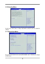
Page 31: ...urity Menu Security menu allow users to change administrator password and user password settings 3 11 Save Exit Menu Save Exit menu allows user to load optimal defaults save or discard your changes to...

Page 32: ...to update and flash the BIOS The system will restart automatically when BIOS is upgraded Solution2 Updating BIOS under Windows operating system 1 Download Windows version BIOS from our website 2 Unzip...

Page 33: ...Magic Install supports Windows XP Vista 7 z Take the attached DVD and insert it into DVD ROM driver the installation shall auto run If the menu does not appear double click MY COMPUTER double click CD...

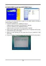
Page 34: ...isk root directory For windows XP vistaX32 Copy CD intel6x pch_ahci_raid f6flpy64 all files to empty boot disk root directory For windows xp64 vistaX64 2 Please going to BIOS setup Advanced Menu SATA...

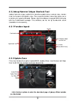
Page 35: ...d package This software can be run by double click which installation is unnecessary 4 3 1 Function layout 4 3 2 Update Zone This zone includes four parts Update BIOS Update Driver User Manual and Hel...

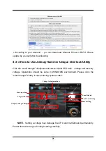
Page 36: ...to adjust CPU ratio voltage and memory voltage Operations should be done in WINDOWS environment Please click the small triangle slowly in case causing system crash NOTE Setting a voltage may damage t...

Page 37: ...g These save values will be run when rebooting For system stability all changes made in Hammer tool will not be saved to BIOS settings 4 3 4 Monitor Zone The function of Monitor zone is generating ale...

Page 38: ...cludes four parts Memory Info CPU Info HDD Info Motherboard Info You can learn relevant hardware information by moving mouse cursor on these four options NOTICE The above driver screen and operation s...

Reviews: