background image

ii

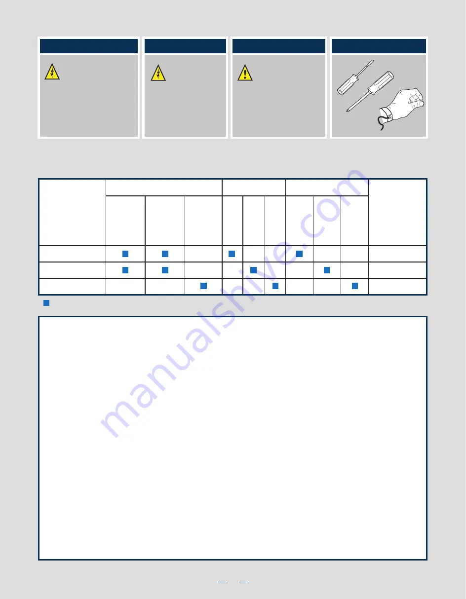
Warning


Read all caution and safety 


statements in this document 


before performing any of the 

instructions.  Also see the 

Intel

®


Server Board and Server Chassis 

Safety Information

 document at:

http://www.intel.com/support/

motherboards/server/sb/cs-010770

.htm


for complete safety information.

Warning

           Installation and service

           of this product to be

           performed only by

qualified service personnel

to avoid risk of injury from

electrical shock or energy

hazard.

Caution


Observe normal ESD

            [Electrostatic Discharge]

            procedures during system

integration to avoid possible

damage to server board and/or

other components.

Tools Required

        Anti-static

wrist strap

     Phillips*

screwdriver

Flat Blade

screwdriver

Intel is a registered trademark of Intel Corporation or its subsidiaries in the United States and other countries.  *Other names and brands may be claimed as the 

property of others.  Copyright © 2012, Intel Corporation. All rights reserved.

Thermal Operation and Configuration Requirements

To keep the system operating within supported maximum thermal limits, the system must meet the following operating and 
configuration guidelines:

Intel

® 

Server System P4000SC Family Product Configuration

= Configuration Feature

4 x 3.5"

Fixed

4 x 3.5"

Hot

Swap

8 x 3.5"

Hot

Swap

Hard Drive

System Fan

One

Fixed

550W

Two

Hot Swap

750W

Two

Hot Swap

460W

RMM4 Lite

RMM4

Power Supply

P4304SC2SFEN

P4304SC2SHDR

P4308SC2MHGC

Intel® Server

System

Intel®

Remote

Management

Module

Five

Hot Swap

System

Fans

(80 x 38 mm)

One

Fixed

PCI Zone

Fan

(92 x 32 mm)

One

Fixed

CPU Zone

Fan

(92 x 32 mm)

Thermal Operation and Configuration Requirements

To keep the system operating within supported maximum thermal limits, the system must meet the following operating and configuration 
guidelines:

• Ambient in-let temperature cannot exceed 35º C and should not remain at this maximum level for long periods of time.  Doing so 
    may affect long term reliability of the system.

• The CPU-1 processor and CPU heatsink must be installed.  


DIMM Population on CPU-1: 

Install DIMMs in order; Channels A, B, and C. Start with 1st DIMM slot (blue) on each                                           

    channel.

• 

DIMM Population on CPU-2: 

Install DIMMs in order; Channels D, E, and F. Start with 1st DIMM slot (blue) on each   

    channel.

• All hard drive bays must be populated. Hard drive carriers either can be populated with a hard drive or supplied drive blank.

• The air duct must be installed at all times.

• In single power supply configurations, the second power supply bay must have the supplied filler blank installed at all times.

• The system top-cover must be installed at all times.

Summary of Contents for P4304SC2SFEN

Page 1: ...ts If you are not familiar with ESD Electrostatic Discharge procedures used during system integration see the complete ESD procedures described in your Service Guide This guide and other supporting do...

Page 2: ...This page is intentionally left blank...

Page 3: ...ve 6 Install PCI e Card Assembly 7 Install Intel Remote Management Module 4 NIC optional 9 Install RMM4 EMI Cover optional 9 Install Alternate Serial Port optional 9 Install Intel RAID Smart Battery o...

Page 4: ...ation Configuration Feature 4 x 3 5 Fixed 4 x 3 5 Hot Swap 8 x 3 5 Hot Swap Hard Drive System Fan One Fixed 550W Two Hot Swap 750W Two Hot Swap 460W RMM4 Lite RMM4 Power Supply P4304SC2SFEN P4304SC2SH...

Page 5: ...5 25 Peripheral Bays Server Board P Intel Remote Management Module 4 Lite Q EMI Cover B A F G H I C D E J K L M N P Q O NOTE Airduct is not shown Intel Server System P4304SC2SFEN System Features and C...

Page 6: ...ap Power Supply Two I O Ports Alternate Serial Port Knockout PCI Add in Board Slot Covers AC Input Power Connector Two RMM4 Knockout Alternate RMM4 Knockout A Kensington Cable Lock Mounting Hole Padlo...

Page 7: ...d stop Similarly loosen screws 3 and 4 Repeat steps A and B by giving each screw two rotations each time until all screws are loosened Using a 2 Phillips screwdriver start with screw 1 and loosen it b...

Page 8: ...wn Install the Processor s continued B Open the Load Plate Open the load plate as shown A B A B Push the rear tab with your finger tip to bring the front end of the load plate up slightly C Remove the...

Page 9: ...For a list of supported memory see the tested memory list at http serverconfigurator intel com default aspx Install DIMM Memory Modules Continued To Install DIMMs Open both DIMM socket levers C A D E...

Page 10: ...cooling With the lever open insert the hard disk drive assembly into the cage opening and push until the locking lever engaged Push in the lever to lock it into place then close the door E F TOP BREA...

Page 11: ...s secured by the chassis Make sure the PCI e card is secured into the slot under the PCI e Card Retainer NOTE Screws are recommended to secure double width cards with chassis back panel 10a Install PC...

Page 12: ...er Board B Server Board C D Install Full length PCI Card 4 5 For chassis with hotswap drive cage remove the drive cage and the EMI cover insert the fan assembly see letter 3a and then install the driv...

Page 13: ...A A Attach the metal fastening bracket to Intel Dedicated Server Management NIC module and secure the bracket with two screws B Remove the alternate RMM4 knock out by pressing the knock out from insi...

Page 14: ...in the direction shown and pull out of the system by the handle NOTE Applies only to the chassis with hot swap power supply configuration 16 Rack Mount Con guration optional If you intend to configur...

Page 15: ...ers and Operating System Install A Con rm BIOS Version Look on the Server System Management screen in the BIOS Setup Utility to determine the installed BIOS version Compare this to the versions at htt...

Page 16: ...e D Connect the I2 C cable to I2 C connector on backplane A Connect Mini SAS data cables B Connect two power cables C NOTE Refer to the documents which come with your server board and or RAID controll...

Page 17: ...ctor On Server Board H PMBus Cable I HSBP_I2 C Cable J PCI Zone System FAN K CPU Zone System FAN Description A CPU1 CPU2 Power Cable B Server Board Main Power Cable C Backplane Power Cable D ODD Power...

Page 18: ...G63272 001...

Reviews: