Figures
Intel
®
Server Board S1200KP Product Guide
vii
Figures
Figure 1. Intel
®
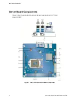
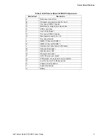
Server Board S1200KP Components ............................................................ 4
Figure 2. LAN Connector LEDs ........................................................................................... 10
Figure 3. Location of the Standby Power Indicator .............................................................. 16
Figure 4. Installing the I/O Shield......................................................................................... 20
Figure 5. Intel
®
Server Board S1200KP Mounting Screw Hole Locations ............................. 21
Figure 6. Unlatch the Socket Lever ..................................................................................... 22
Figure 7. Lift the Load Plate ................................................................................................ 23
Figure 8. Remove the Processor from the Protective Cover ................................................ 24
Figure 9. Install the Processor ............................................................................................. 24
Figure 10. Secure the Load Plate in Place .......................................................................... 25
Figure 11. Connecting the Processor Fan Heat Sink Power Cable to the Processor Fan
Header .......................................................................................................................... 26
Figure 12. Dual Channel Memory Configuration Example ................................................... 27
Figure 13. Use DDR3 DIMMs .............................................................................................. 28
Figure 14. Installing a DIMM ................................................................................................ 29
Figure 15. Installing a PCI Express* x16 Graphics Card ...................................................... 31
Figure 16. Removing a PCI Express* x16 Graphics Card .................................................... 32
Figure 17. Connecting a SATA Drive ................................................................................... 33
Figure 18. Internal Headers ................................................................................................. 34
Figure 19. Location of the Chassis Fan Header ................................................................... 37
Figure 20. Connecting Power Supply Cables ...................................................................... 38
Figure 21. Location of the BIOS Configuration Jumper Block .............................................. 39
Figure 22. Removing the Battery ......................................................................................... 42


