background image


Figure 2. Opening Processor Socket Lever


8.


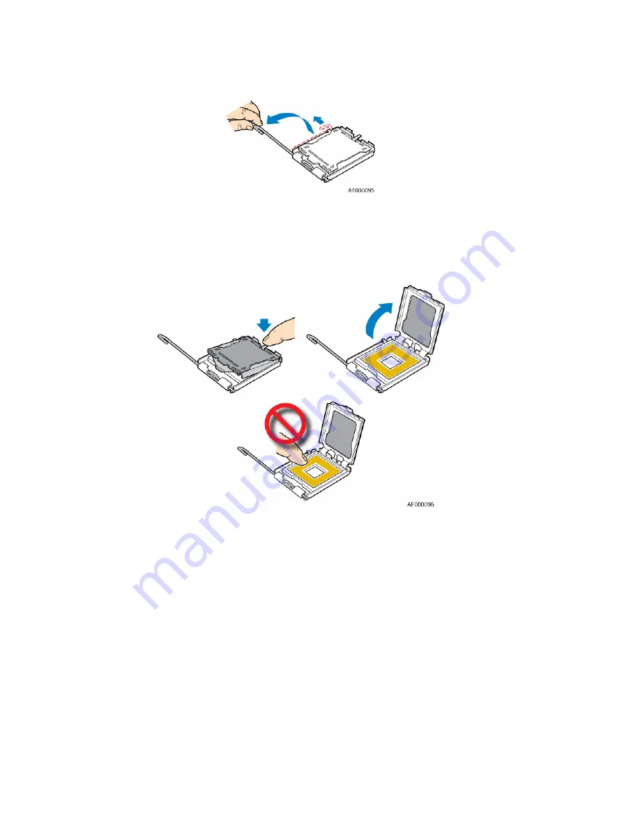
Push down on the rear tab of the load plate to swing the front of the load plate up slightly. Fully 
open the load plate. See 

Figure 3


Figure 3. Opening Load Plate


9.


  If the protective cover is attached from the load plate, remove it and store it for future use. See 

Figure 4.


Summary of Contents for 5000 Series

Page 1: ...SD protection by wearing an antistatic wrist strap attached to chassis ground any unpainted metal surface on your server workstation when handling parts ESD and handling boards Always handle boards carefully They can be extremely sensitive to ESD Hold boards only by their edges After removing a board from its protective wrapper or from the server workstation place the board component side up on a ...

Page 2: ...nents necessary to access the processor sockets See the documentation that came with your chassis for instructions on removing chassis components 7 Push down on the lever attached to the processor socket While holding the lever down pull it towards the center of the board to disengage the lever from the hook Fully open the lever See Figure 2 ...

Page 3: ... the rear tab of the load plate to swing the front of the load plate up slightly Fully open the load plate See Figure 3 Figure 3 Opening Load Plate 9 If the protective cover is attached from the load plate remove it and store it for future use See Figure 4 ...

Page 4: ... the processor in the socket with the processor cutouts matching the processor socket notches See Figure 5 Figure 5 Setting Processor in Place 12 Close the load plate 13 Close the socket lever Push downward on the socket lever while pushing it toward the center of the processor socket to engage it under the hook on the processor socket ...

Page 5: ...nd a cable that needs to be connected to the server board AF000099 Figure 6 Active Heat Sink Cable Not Shown Use the following steps to install a heat sink 1 Set the heat sink over the processor lining up the four captive screws with the four posts surrounding the processor 2 Loosely screw in the captive screws on the heat sink corners in the order shown by Figure 7 Do not fully tighten one screw ...

Page 6: ...per fan header location 5 Reinstall and reconnect any parts you removed or disconnected to reach the processor sockets See the documentation that came with your chassis for instructions on installing chassis components 6 Replace the chassis cover and reconnect the AC power cord See the documentation that came with your chassis for instructions on installing the cover ...

Reviews: