Model No: M150 Plus
Customer: INTEK Rev No: A
10
2.
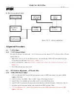
Turn the RF S.S.G output for 100uV without modulation.
3.
Adjust RV6 for 9 characters displayed at the RX signal strength of the LCD.
4.
Turn the RF S.S.G level output increase 30dB, the RX signal strength should up to +30 position.
4.2.5 Maximum S/N Detector & ANL detection:
1. UUT set to FM CH22
,
output of RF signal generator to antenna input terminal. RF Gain set to maximum, Squelch set
to minimum, compander set off. (M-150 W/O Compander)
2.
Set RF S.S.G Freq.: 27.225MHz
,
Mod.:
±
1.2KHz
,
Fmod.: 1KHz, Output level: 1mV.
3.
The Volume control turn to 0.5 watts audio output for reference A dB.
4.
Then off the Modulation, here the audio output for reference B dB. A-B for S/N
≥
35dB.
5.
Compander set to On, repeat above item 3 and 4, A-B for S/N
≥
50dB. (M-760 only)
6.
UUT set to AM CH22, set RF S.S.G Mod. for 60%. Compander set Off. Repeat above item 3 and 4, A-B for S/N
≥
35dB; Compander set to On, repeat above item 3 and 4, A-B for S/N
≥
50dB. (M-760 only)
7.
UUT set to AM CH22, set RF S.S.G mod for 30%. RF level set 5.0uV. ESP set off. RF Gain set to maximum, Squelch
set to minimum. ANL set off, Noise generater (pulse 1us; width 100ms; output level 1.0Vrms) set to on and connect to
the antenna socket with network combinator.
8.
Set audio output level for 0.8Vrms for 0dB reference, RF S.S.G MOD. turn off, set ANL to ON, the audio output
should be drop 6dB or below.
4.3 TX Section Alignment.
4.3.1 TX output power and Frequency Alignment:
1.
UUT set to FM EU CH19
,
Antenna connect to the RF power-meter input terminal.
2.
Set UUT to TX mode, adjust the IFT L8 and L9 for TX power output maximum, and then adjust the RV4 check the
output TX power for 4.0W.
3.
Set UUT turn to AM mode, check the TX power output for 0.7 to 1.3W.
4.
Change to channel to UK band “U40” (27.99125MHz), Adjust the trimmer capacitor CT1 to 27.99125MHz
±
50Hz
on frequency counter. The UUT turn to EU CH19, check the TX carrier frequency should 27./- 300Hz.
5.
TX harmonics adjust and checking, turn to FM CH19, adjust L24 for 2
nd
harmonic -36dBm below.
4.3.2 TX Signal Meter Indicator Alignment.
1.
UUT set to AM CH19
,
input of power-meter to antenna input terminal.
2.
Set UUT to TX mode, adjust the RV2 for “4” characters displayed at the TX signal strength of the LCD display.
4.3.3 TX modulation Deviation Alignment:


