background image


9


Getting to Know the AV Receiver


—Continued


T


Input selector buttons (44)


Select the following input sources: Multi CH, DVD, 
Video 1, Video 2, Video 3, Video 4, Tape, Tuner, or 
CD.

The [Multi CH] button selects the multichannel 
DVD input.


U


Setup Mic (37)


The automatic speaker setup microphone connects 
here.


V


Video 4 Input (30, 57)


Used to connect a camcorder, game console, and so 
on. There are jacks for optical digital audio, 
S-Video, composite video, and analog audio.

For detailed information, see the pages in parentheses.


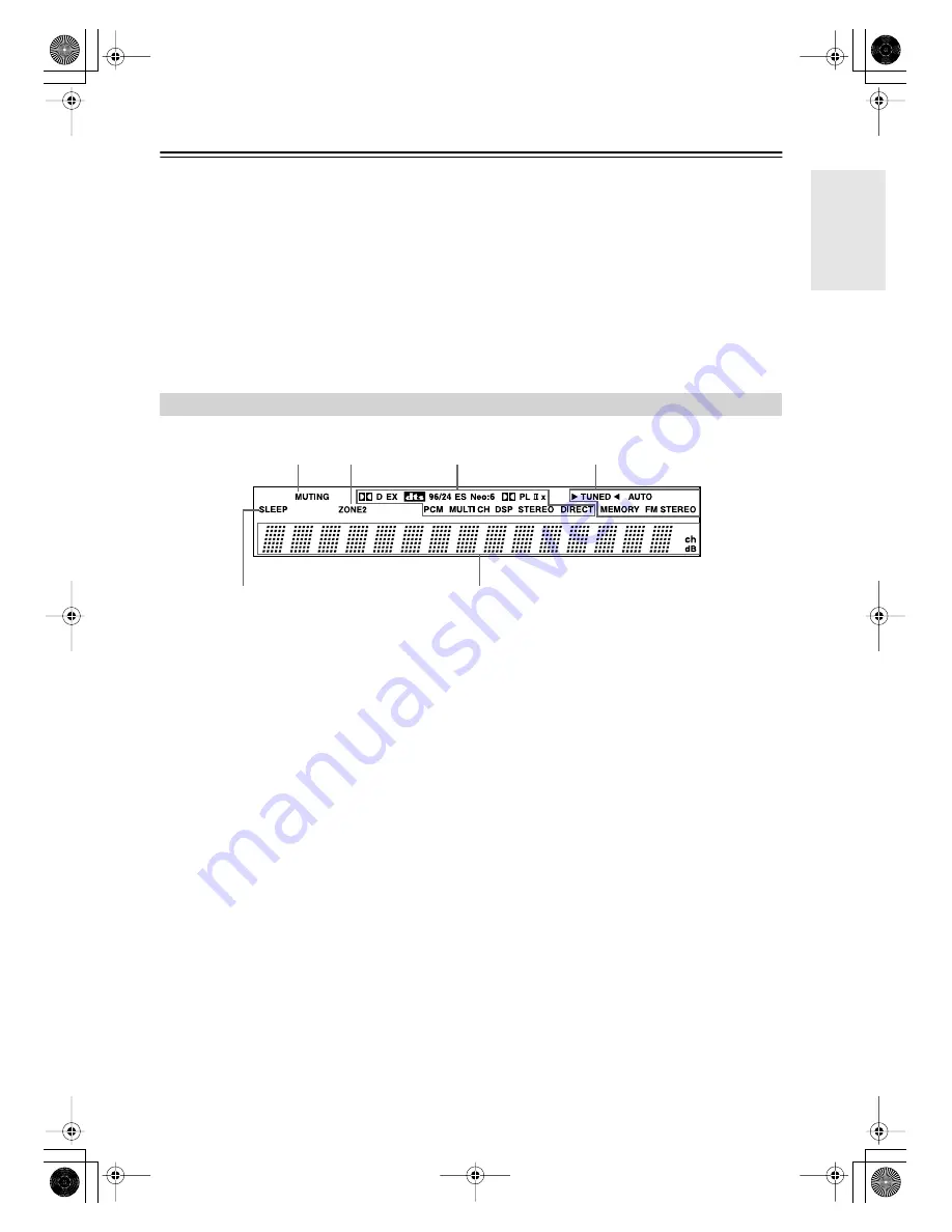
1


MUTING indicator (52)


Flashes while the AV receiver is muted.


2


ZONE 2 indicator (75)


Lights up when Zone 2 is on.


3


Listening mode and format indicators (54)


Show the selected listening mode and the format of 
digital input signals.


4


Tuning indicators (45)

TUNED (45): 


Lights up when tuned to a radio sta-

tion.


AUTO (45): 


For AM and FM radio, lights up when 

Auto Tuning mode is selected, and disappears when 
Manual Tuning mode is selected.


MEMORY (50): 


Lights up when presetting radio 

stations.


FM STEREO (45): 


Lights up when tuned to a ste-

reo FM station.


5


SLEEP indicator (53)


Lights up when the Sleep function has been set.


6


Message area


Displays various information about the selected 
input source.


Display

2

1

3

4

5

6

DTR-5.6.book Page 9 Thursday, September 22, 2005 5:07 PM

Summary of Contents for DTR-5.6

Page 1: ...DTR 5 6 Instruction Manual AV Receiver DTR 5 6 book Page 1 Thursday September 22 2005 5 07 PM ...

Page 2: ...mally by following the operating instructions Adjust only those controls that are covered by the operating instructions as an improper adjustment of other controls may result in damage and will often require extensive work by a qualified technician to restore the apparatus to its normal operation E If the apparatus has been dropped or damaged in any way and F When the apparatus exhibits a distinct...

Page 3: ...the case of a power failure Although no batteries are required the AV receiver must be plugged into an AC outlet in order to charge the backup system Once it has been charged the AV receiver will retain the settings for several weeks although this depends on the environment and will be shorter in humid climates For U S models FCC Information for User CAUTION The user changes or modifications not e...

Page 4: ...Indoor FM antenna AM loop antenna Power cord Plug type varies from country to country Speaker cable labels Front Left Front Left SP B Zone 2 Left SP B Zone 2 Left Surround Right Surround Right Surround Back Right Surround Back Right Zone 2 Right Zone 2 Right Front Left Front Left SP B Zone 2 Left SP B Zone 2 Left Front Right Front Right SP B Zone 2 Right SP B Zone 2 Right Front Right Front Right S...

Page 5: ...quency Step Setup on some models 43 Basic Operation Playing Your AV Components 44 Listening to the Radio 44 Listening to AM FM Stations 45 Listening to XM Satellite Radio 46 Presetting AM FM Stations and XM Channels 50 Using the Multichannel DVD Input 51 Common Functions 52 Setting the Display Brightness 52 Adjusting Speaker Levels 52 Muting the AV Receiver 52 Using the Sleep Timer 53 Using Headph...

Page 6: ...enus Preprogrammed remote controller for use with other AV components Remote controller Learning function Remote controller Macro function Powered Zone 2 3 12 V trigger outputs A B C 2 IR inputs A B 1 output 1 Manufactured under license from Dolby Laboratories Dolby Pro Logic Surround EX and the double D symbol are trademarks of Dolby Laboratories 2 DTS DTS 96 24 DTS ES and Neo 6 are trade marks o...

Page 7: ...the same room or the AV receiver is installed close to equipment that uses infrared rays the remote control ler may not work reliably Don t put anything on top of the remote controller such as a book or magazine because a button may be pressed continuously thereby draining the batteries The remote controller may not work reliably if the AV receiver is installed in a rack behind colored glass doors...

Page 8: ...he connected TV M Arrow Tuning Preset and Enter buttons When AM FM or XM is selected the Tuning buttons are used for radio tuning and the Pre set buttons are used to select radio presets see page 50 With the onscreen setup menus they work as arrow buttons and are used to select and set items The Enter button is also used with the onscreen setup menus N Return button Selects the previously displaye...

Page 9: ...lashes while the AV receiver is muted 2 ZONE 2 indicator 75 Lights up when Zone 2 is on 3 Listening mode and format indicators 54 Show the selected listening mode and the format of digital input signals 4 Tuning indicators 45 TUNED 45 Lights up when tuned to a radio sta tion AUTO 45 For AM and FM radio lights up when Auto Tuning mode is selected and disappears when Manual Tuning mode is selected M...

Page 10: ...M antenna on North American model This jack is for connecting an XM digital antenna sold separately G AM ANTENNA These push terminals are for connecting an AM antenna H MONITOR OUT The S Video or composite video jack should be connected to a video input on your TV or projector I FM ANTENNA This jack is for connecting an FM antenna J 12V TRIGGER OUT A B C These outputs can be connected to the 12 vo...

Page 11: ... composite video input jacks for con necting the video signal and stereo FRONT and multichannel 5 1 7 1 jacks for connecting the ana log audio signals T ZONE 2 SPEAKERS These terminal posts are for connecting speakers in Zone 2 U PRE OUT FRONT L R SURROUND L R CENTER SUBWOOFER and SURR BACK L R This 5 1 7 1 analog audio output can be connected to the analog audio input on another power ampli fier ...

Page 12: ...e modes you can control a TV and VCR You must enter the appropriate remote control code first see page 79 Cable CDR and SAT MD Modes In Cable CDR mode you can control an Integra CD recorder or a cable TV receiver In SAT MD mode you can control an Integra MD recorder or a satellite TV receiver You must enter the appropriate remote control code first see page 79 Note Some of the remote controller op...

Page 13: ...ne 2 O Remote Mode buttons 12 Used to select the remote controller modes When a remote controller button is pressed the Remote Mode button of the currently selected mode lights up P Sleep button 53 Used with the Sleep function Q Menu button on North American model 47 Selects the search mode for XM Satellite Radio R VOL button 44 Adjusts the volume of the AV receiver regardless of the currently sel...

Page 14: ... on I Playback buttons From left to right Previous Play Next Rewind Pause Stop Fast Forward Slow Reverse and Slow Forward J Repeat button Used with the repeat playback function K Audio button Selects foreign language soundtracks and audio for mats e g Dolby Digital or DTS L Open Close button Opens and closes the disc tray M Clear button Cancels functions and clears entered numbers N Menu button Di...

Page 15: ... and times for locating specific points D Arrow and Enter buttons Used with some components E Disc button Selects discs on a CD changer F Display button Displays information about the current disc or track including elapsed time remaining time total time and so on G Playback buttons From left to right Previous Play Next Rewind Pause Stop and Fast Forward H Rec button Starts recording I Repeat butt...

Page 16: ... Previous button Restarts the current song Press it twice to select the previous song G Pause button Pauses playback With 3rd generation iPods it works as a Play Pause button H Rewind button Press and hold to rewind I Playlist buttons Used to select the previous or next playlist on the HDD compatible component J Repeat button Used with the repeat function K Menu button Used to access menus L Play ...

Page 17: ...rs Subwoofer The subwoofer handles the bass sounds of the LFE Low Frequency Effects channel The volume and quality of the bass output from your subwoofer will depend on its posi tion the shape of your listening room and your listening position In general a good bass sound can be obtained by installing the subwoofer in a front corner or at one third the way along the wall as shown Tip To find the b...

Page 18: ...ofer Using a suitable cable connect the AV receiver s SUB WOOFER PRE OUT to the input on your powered sub woofer If your subwoofer is unpowered and you re using an external amplifier connect the SUBWOOFER PRE OUT to the amp s input Attaching the Speaker Labels The AV receiver s positive speaker terminals are color coded for ease of identification The negative speaker terminals are all black The su...

Page 19: ...sitive terminals to only positive terminals and negative terminals to only nega tive terminals If you get them the wrong way around the sound will be out of phase and will sound unnatural Unnecessarily long or very thin speaker cables may affect the sound quality and should be avoided Be careful not to short the positive and negative wires Doing so may damage the AV receiver Don t connect more tha...

Page 20: ... and adjust the position of the FM antenna to achieve the best possible reception 2 Use thumbtacks or something similar to fix the FM antenna into position Caution Be careful that you don t injure yourself when using thumbtacks AM antenna push terminals FM antenna jack Insert the plug fully into the jack Insert the plug fully into the jack Thumbtacks etc Connecting the AM Loop Antenna 1 Assemble t...

Page 21: ...ent electrical shock haz ards Using a TV FM Antenna Splitter It s best not to use the same antenna for both FM and TV reception as this can cause interference problems If cir cumstances demand it use a TV FM antenna splitter as shown If good reception cannot be achieved using the supplied AM loop antenna an outdoorAM antenna can be used in addition to the loop antenna as shown OutdoorAM antennas w...

Page 22: ...omposite video Left white Right red Yellow Right Wrong Video Cable Jack Description Component video cable Component video separates the luminance Y and color difference signals PR PB providing the best picture quality Some TV manufacturers label their component video jacks slightly differently S Video cable S Video separates the luminance and color signals and provides better picture quality than ...

Page 23: ... upconvert composite video and S Video input signals and output them from the COMPONENT VIDEO OUT see page 40 Video Signal Flow Chart Audio Connection Formats Audio equipment can be connected to the AV receiver by using any of the following audio connection formats analog optical coaxial or analog multichannel When choosing a connection format bear in mind that the AV receiver does not convert dig...

Page 24: ...ut Better MONITOR OUT V Composite video input Standard VIDEO 3 IN L R Analog audio L R output DIGITAL COAXIAL IN 2 Digital coaxial output DIGITAL OPTICAL IN 2 Digital optical output Step 1 Video Connection Choose a video connection that matches your TV or and then make the connection A B C Step 2 Audio Connection Choose an audio connection that matches your TV or and then make the connection a b c...

Page 25: ...gital coaxial output DIGITAL OPTICAL IN 3 Digital optical output Step 1 Video Connection Choose a video connection that matches your DVD player or and then make the connection If you use connection you must connect the AV receiver to your TV with the same type of connection A B C A Step 2 Audio Connection Choose an audio connection that matches your DVD player or and then make the connection a b c...

Page 26: ...ables to connect the AV receiver s DVD IN FRONT L R CENTER SURROUND L R SURR BACK L R and SUBWOOFER jacks to the 7 1 channel analog audio output on your DVD player If your DVD player has a 5 1 channel analog audio output don t connect anything to the AV receiver s SURR BACK L R jacks See Using the Multichannel DVD Input on page 51 for setup and operation R FRONT L L R SURROUND CENTER SUB WOOFER FR...

Page 27: ...omponent video output Best VIDEO 1 IN S S Video output Better VIDEO 1 IN V Composite video output Standard VIDEO 1 IN L R Analog audio L R output DIGITAL COAXIAL IN 2 Digital coaxial output DIGITAL OPTICAL IN 1 Digital optical output Step 1 Video Connection Choose a video connection that matches your VCR or DVD recorder or and then make the connection If you use connection you must connect the AV ...

Page 28: ... input Standard VIDEO 1 OUT L R Audio L R input DIGITAL OPTICAL OUT Digital optical input Step 1 Video Connection Choose a video connection that matches your VCR or DVD recorder or and then make the connection The video source to be recorded must be connected to the AV receiver via the same type of connection A B Step 2 Audio Connection Choose an audio connection that matches your VCR or DVD recor...

Page 29: ...coaxial output DIGITAL OPTICAL IN 2 Digital optical output Step 1 Video Connection Choose a video connection that matches the video source or and then make the connection If you use connection you must connect the AV receiver to your TV with the same type of connection A B C A Step 2 Audio Connection Choose an audio connection that matches the video source or and then make the connection a b c a b...

Page 30: ...t Digital Digital optical output Step 1 Video Connection Choose a video connection that matches the camcorder or console or and then make the connection A B Step 2 Audio Connection Choose an audio connection that matches the camcorder or console or and then make the connection a b Digital S Video Input Input OPTICAL OUT Audio Input Video Input L R S VIDEO OUT AUDIO OUT VIDEO OUT L R b A a B Camcor...

Page 31: ...on AV receiver Signal flow CD player CD IN L R Analog audio L R output DIGITAL COAXIAL IN 2 Digital coaxial output DIGITAL OPTICAL IN 3 Digital optical output COAXIAL IN 2 COAXIAL OUT AUDIO OUT L R OPTICAL OUT OPTICAL IN 3 L R IN CD b c a Step 1 Choose a connection that matches your CD player or and then make the connection a b c CD player Connect one or the other a b c a b a c a b c DTR 5 6 book ...

Page 32: ...e as shown Turntable with an MC Moving Coil Cartridge Use an analog audio cable to connect an unused audio input on the AV receiver to the audio outputs on your phono preamp Use another analog audio cable to con nect the phono preamp s inputs to your MC head amp s outputs And use another analog audio cable to connect the MC head amp s inputs to your turntable as shown Connecting a Turntable IN L R...

Page 33: ...CDR MD or DAT recorder TAPE IN L R TAPE OUT L R Analog audio L R output Analog audio L R input DIGITAL COAXIAL IN 2 Digital coaxial output DIGITAL IN OPTICAL IN 3 Digital optical output DIGITAL OPTICAL OUT Digital optical input Connecting a Power Amplifier COAXIAL IN 2 COAXIAL OUT AUDIO IN L R OPTICAL OUT OPTICAL IN 3 OPTICAL IN L R IN TAPE AUDIO OUT L R L R TAPE OPTICAL b c a a d Step 1 Choose a ...

Page 34: ...her capable Integra components pointing the remote controller at the AV receiver s remote control sensor instead of the component You must enter the appropriate remote control code first see page 80 Notes Use only cables for connections cables are supplied with Integra players DVD CD etc Some components have two jacks You can connect either one to the AV receiver The other jack is for connecting a...

Page 35: ... power cord connect all of your speakers and AV components Turning on the AV receiver may cause a momentary power surge that might interfere with other electrical equipment on the same circuit If this is a problem plug the AV receiver into a different branch circuit Do not use a power cord other than the one supplied with the AV receiver The supplied power cord is designed exclusively for use with...

Page 36: ...volume before you turn it off Remote controller AV receiver or Smooth Operation in a Few Easy Steps To ensure smooth operation here s a few easy steps to help you configure the AV receiver before you use it for the very first time These settings only need to be made once Do the automatic speaker setup this is essential See Automatic Speaker Setup on page 37 Have you connected a component to compon...

Page 37: ...ohms change the minimum speaker impedance setting before running the automatic speaker setup see page 42 2 Put the speaker setup micro phone in the listening position Notes Make sure the microphone is hori zontal If there s an obstacle between the microphone and any speaker the automatic setup will not work cor rectly Set up the room as you would when enjoying a DVD Positioning the microphone clos...

Page 38: ...ts Select this to save the results then con tinue with step 5 Normally you d select this option Check the Results Select this if you want to view the results See Checking the Results on page 39 Retry Select this if you want to run the auto matic speaker setup again starting from step 3 Retry with Test noise Level up Select this to run the automatic speaker setup again but with the test tone louder...

Page 39: ...it s posi tioned low down on the floor and outputting very low frequency sounds its output may not be detected prop erly If the subwoofer abbreviation SW appears on the Warning screen under Not Detect turn up the sub woofer s volume and run the automatic speaker setup again If the subwoofer has a built in crossover set it to the highest crossover frequency If it has an LPF filter switch set it to ...

Page 40: ... VIDEO VIDEO 4 VIDEO 2 2 3 1 4 1 1 Press the Receiver button fol lowed by the Setup button The main menu appears onscreen 2 Use the Up and Down buttons to select 1 Component Video and then press Enter The Component Video menu appears 3 Use the Up and Down buttons to select an input selec tor and use the Left and Right buttons to select IN1 Select if the video compo nent is connected to COM PONENT ...

Page 41: ...the Setup button The main menu appears onscreen 2 2 3 1 4 1 2 Use the Up and Down buttons to select 2 Digital Input and then press Enter The Digital Input menu appears 3 Use the Up and Down buttons to select an input selec tor and then use the Left and Right buttons to select Coax 1 Coax 2 Opt 1 Opt 2 Opt 3 or No analog For input selectors that you want to use with an analog input select No Inputs...

Page 42: ...tor button about 3 seconds to change the setting Repeat this step to select MD CDR or HDD For the Tape input selector the setting changes in this order For the Video 3 input selector the set ting changes in this order VIDEO 3 HDD 1 2 1 2 or or TAPE MD CDR HDD Minimum Speaker Impedance 1 Press the Receiver button fol lowed by the Setup button The main menu appears onscreen 2 Use the Up and Down but...

Page 43: ...this to automatically detect theTV system from the video input signals NTSC Select if the TV system in your area is NTSC PAL Select if the TV system in your area is PAL 4 Press the Setup button Setup closes 8 Hardware Setup a PoweredZone2 NotAct b V Format Auto c TV Format Auto d AM Freq Step 9kHz e Remote ID 1 b Zone2 Out Fixed AM Frequency Step Setup on some models 1 Press the Receiver button fo...

Page 44: ...atch a DVD or other video source on your TV select the video input that s con nected to the AV receiver s COMPONENT VIDEO OUT or MONITOR OUT On some DVD players you may need to change the digital setting 3 To adjust the volume use the Master Volume control or the remote con troller s VOL button Since the AV receiver is designed for home theaters it has a wide volume range for precise adjustment Th...

Page 45: ... Tuning mode and listen to the station in mono Displaying AM FM Radio Information Listening to AM FM Stations 1 Use the Tuner input selector button to select AM or FM In this example FM has been selected Actual display depends on country 1 Press the Tuning Mode button so that the AUTO indicator appears on the display 2 Press the Tuning Up or Down button Searching stops when a station is found Tuni...

Page 46: ...ou can purchase the XM Connect and Play antenna from the XMWeb site at http www xmradio com Connect the Connect and Play antenna to the XM antenna jack on the rear panel Put the XM antenna by a southerly facing window with nothing obstructing its path to the sky Signing Up for XM Satellite Radio Before you can use XM Satellite Radio you must first sign up for an account You ll need a major credit ...

Page 47: ... XM If CHECK ANTENNA appears on the display make sure the XM antenna is connected properly 2 Press the Menu button to select Channel Search mode 3 Use the Up and Down buttons to select a channel You can also use the Left and Right buttons to select a category 2 1 1 3 Return Channel name Channel number 1 Press the Receiver Remote Mode button and then press the Tuner Input Selector button repeatedly...

Page 48: ...lector button repeatedly to select XM If CHECK ANTENNA appears on the display make sure the XM antenna is connected properly 2 Use the Tuning Up and Down buttons to select a chan nel In Channel Search mode you can select any channel In Category Search mode you can only select channels from the currently selected category 1 On the AV receiver press the Display button repeatedly to cycle through the...

Page 49: ...e AV receiver is tuning or decoding audio or text data Please wait The XM channel you selected is not currently broadcast ing Select another channel 1 Press the remote controller s Receiver button followed by the Setup button 2 Use the Up and Down buttons to select 4 Input Setup and then press Enter 3 Use the Up and Down buttons to select 2 XM Antenna Aiming and then press Enter 1 1 5 2 3 4 Input ...

Page 50: ...econds use the Preset buttons to select a preset from 1 through 40 4 Press the Memory button again to store the station or channel The station or channel is stored and the preset number stops flashing Repeat this procedure for all of your favoriteAM FM radio stations and XM channels 2 4 3 1 To select a preset use the Preset buttons or the remote controller s CH button 1 Select the preset that you ...

Page 51: ...fects signals con nected to the SUBWOOFER input jack of the multichan nel DVD input You can select 0 dB 5 dB 10 dB or 15 dB If you find that your subwoofer is too loud try the 10 dB or 15 dB setting Using the Multichannel DVD Input Press the Receiver Remote Mode button followed by the Multi CH button The MULTI CH indicator appears on the display Audio from the multichannel DVD input will now be us...

Page 52: ...ss the remote control ler s Muting button again or adjust the volume The output is unmuted and the MUTING indicator goes off Muting is cancelled when the AV receiver is set to Standby Tip You can choose how much the output is muted by using the Muting Level preference see page 69 Setting the Display Brightness Press the Dimmer button repeatedly to select Normal Dim Dimmer Muting CH Sel Level Sleep...

Page 53: ...ally be displayed If the input signal is analog no format information is displayed If the input signal is PCM the sampling fre quency is displayed If the input signal is digital but not PCM the signal format is displayed Interpreting Surround Channel Information A The number of front channels front left front right and center B The number of surround channels surround left and surround right If th...

Page 54: ...er to widen the stereo image and simulates the natural reverberation of a large hall Unplugged Suitable for acoustic instruments vocals and jazz this mode emphasizes the front stereo image giving the impression of being right in front of the stage Studio Mix Suitable for rock or pop music listening to music in this mode creates a lively sound field with a powerful acous tic image like being at a c...

Page 55: ...ormal DTS Multich analog 3 2 1 2 2 1 2 0 1 0 1 1 Other 3 2 1 2 2 1 2 0 DTS ES Discrete Matrix CD TV radio cassette etc DVD DTV etc DVD CD etc DVD Direct Stereo Mono Multich PLIIx Movie Music Game 3 Neo 6 Cinema Neo 6 Music 4 3 If the Surr Back parameter is set to None or the ZONE 2 SPEAKERS terminals are being used normal Pro Logic II is used 4 Available only when surround speakers are connected D...

Page 56: ...ffects Use them with DVDs that bear the Dolby Digital or DTS logo Dolby Digital PLIIx Music DTS PLIIx Music These modes use the Pro Logic IIx Music mode to expand 5 1 channel Dolby Digital and DTS sources for 6 1 7 1 channel play back Use them with Dolby Digital or DTS 5 1 music sources e g DVD and Dolby Digital TV broadcasts Dolby Digital PLIIx Movie DTS PLIIx Movie These modes use the Pro Logic ...

Page 57: ...g audio and video from two sep arate sources This is possible because only the audio source is switched when an audio only input source such as TAPE TUNER or CD is selected the video source remains the same In the following example audio from the CD player con nected to the CD IN and video from the camcorder con nected to the Video 4 Input Video jack are recorded by the VCR connected to the VIDEO ...

Page 58: ...eference 8 Hardware Setup 3 Speaker Setup 1 Speaker Impedance 2 Speaker Configuration 3 Speaker Distance 4 Level Calibration 5 Equalizer Settings 4 Input Setup VIDEO1 1 Delay 5 Listening Mode Preset 1 DVD 2 VIDEO1 3 VIDEO2 4 VIDEO3 5 VIDEO4 6 TAPE 7 TUNER 8 CD 6 Audio Adjust 1 Tone Control 2 PL x Neo 6 3 Dolby Digital 4 LFE Level 5 Mono Multiplex 7 Preference 1 IntelliVolume 2 Volume Setup 3 OSD S...

Page 59: ... Fltr button again to turn off the Cine Filter function Setup Receiver L Night Cine Fltr Enter Audio Adjust Menu 1 Press the Receiver Remote Mode button followed by the Setup button The main menu appears onscreen 2 Use the Up and Down buttons to select 6 Audio Adjust and then press Enter The Audio Adjust menu appears 3 Use the Up and Down buttons to select a setting and then press Enter The menu f...

Page 60: ... there s not enough surround sound move it backward Center Width With this setting you can adjust the width of the sound from the center speaker when using the Pro Logic II Music or Pro Logic IIx Music listening mode Normally if you re using a center speaker the center channel sound is output by only the center speaker If you re not using a center speaker the center channel sound will be distrib u...

Page 61: ...er is set to Standby LFE Level Setting With this setting you can set the level of the LFE Low Frequency Effects channel for Dolby Digital DTS and MCH Ana multichannel DVD input The level can be set to 20 dB 10 dB or 0 dB default If you find that the low frequency effects are too loud when using one of these sources set the level to 20 dB or dB Mono Multiplex Settings Mono Input Ch This setting det...

Page 62: ...digital format such as Dolby Digital and DTS MCH Ana Specifies the default listening mode for the analog multichannel DVD input This option is only available for the 1 DVD input selector Default Listening Modes 1 Press the Receiver Remote Mode button followed by the Setup button The main menu appears onscreen 2 Use the Up and Down buttons to select 5 Listening Mode Preset and then press Enter The ...

Page 63: ...ion see page 37 Cone diameter 2 Use the Up and Down buttons to select 3 Speaker Setup and then press Enter The Speaker Setup menu appears 3 Use the Up and Down buttons to select Speaker Con figuration and then press Enter The Speaker Config menu appears 4 Use the Up and Down buttons to select a Subwoofer and then use the Left and Right buttons to select Yes Select if a subwoofer is con nected No S...

Page 64: ...d right speakers are small Large Select if the surround back speakers are large None Select if no surround back speakers are connected Notes If the Surround setting in step 7 is set to None this setting cannot be selected If the Surround setting in step 7 is set to Small this setting cannot be set to Large 9 Use the Up and Down buttons to select f SurrBack Ch and then use the Left and Right button...

Page 65: ...ly by the Automatic Speaker Setup function see page 37 These settings are set automatically by the Automatic Speaker Setup function see page 37 2 Use the Up and Down buttons to select 3 Speaker Setup and then press Enter The Speaker Setup menu appears 3 Use the Up and Down buttons to select Speaker Dis tance and then press Enter The Speaker Distance menu appears Note Speakers that you set to No or...

Page 66: ...elect 3 Speaker Setup and then press Enter The Speaker Setup menu appears These settings are set automatically by the Automatic Speaker Setup function see page 37 3 Use the Up and Down buttons to select Level Calibra tion and then press Enter The Level Calibration menu appears and the pink noise test tone is output by the front left speaker Note Speakers that you set to No or None on the Speaker C...

Page 67: ...n Manual The equalizer for each speaker can be set manually If you selected Manual continue with the next step If you selected Off or Auto go to step 8 These settings are set automatically by the Automatic Speaker Setup function see page 37 5 Use the Down button to select b Channel and then use the Left and Right but tons to select a speaker 6 Use the Up and Down buttons to select a frequency and ...

Page 68: ...e Setup button The main menu appears onscreen 2 Use the Up and Down buttons to select 4 Input Setup and then press Enter The Input Setup menu appears Setup Receiver Return Enter 4 Input Setup VIDEO1 1 Delay 3 Use the Up and Down buttons to select Delay and then press Enter The Delay menu appears 4 Press Enter to see the TV pic ture and use the Left and Right buttons to adjust the delay so that the...

Page 69: ...sed see page 52 It can be set to dB default or between 50 dB and 10 dB in 10 dB steps Maximum Vol Z2 Maximum Vol With these preferences you can prevent the volume being set too high by specifying maximum volume levels for the main room and Zone 2 When the Volume Display preference is set to Abso lute the range of MaximumVol is 50 to 99 Z2 Max imum Vol is 50 to 81 When it s set to Relative the rang...

Page 70: ...play and select Interlaced Immediate These settings determine how the operation details are displayed Immediate Display This preference determines whether operation details are displayed onscreen when an AV receiver function is adjusted On Displayed default Off Not displayed Even when On is selected operation details are not out put if the input source is connected to a COMPONENT VIDEO IN Monitor ...

Page 71: ...te ID be sure to set the AV receiver to the same ID Otherwise you won t be able to control it see previous column Remote IDs 1 Press the Receiver Remote Mode button followed by the Setup button The main menu appears onscreen 2 Use the Up and Down buttons to select 8 Hardware Setup and then press Enter The Hardware Setup menu appears Setup TV INPUT Receiver Enter Number buttons Remote indicator 3 U...

Page 72: ...Use the Up and Down buttons to select 2 Digital Input and then press Enter Setup Receiver Enter 3 Use the Up and Down buttons to select an input source that s assigned to a digital input opt or coax and then press Enter The Digital Format menu appears 4 Use the Up and Down buttons to select the input and use the Left and Right buttons to select PCM DTS or Auto PCM The PCM indicator flashes and onl...

Page 73: ... L R jacks to an analog audio input on the amp in Zone 2 Connect the Zone 2 speakers to the speaker terminals on the amp in Zone 2 Using Only Speakers in Zone 2 With this hookup you can enjoy 5 1 channel playback in the main room and a different stereo source in Zone 2 The volume for Zone 2 is set on this AV receiver Hookup Connect your Zone 2 speakers to the AV receiver s ZONE 2 SPEAKERS terminal...

Page 74: ...RS terminals activated When Act is selected and Zone 2 is turned on the speakers connected to the ZONE 2 SPEAKERS terminals will output sound When Zone 2 is turned off even ifAct is selected the surround back speakers will work as normal 4 Press the Setup button Setup closes 8 Hardware Setup a PoweredZone2 NotAct b Zone2 Out Fixed c TV Format Auto d AM Freq Step 9kHz e Remote ID 1 a PoweredZone2 N...

Page 75: ...To select AM FM or XM North American model only press the Tuner input selector button repeat edly To select the same source as that of the main room press the Zone 2 button repeatedly until Zone 2 Sel Source appears 2 To turn off Zone 2 press the Zone 2 Off button 1 2 1 Press the Zone 2 Remote Mode button then point the remote controller at the AV receiver and press the On button Zone 2 turns on a...

Page 76: ...ne 2 Bass You can boost or cut low frequency sounds output by the front speakers from 10 dB to 10 dB in 2 dB steps Treble You can boost or cut high frequency sounds output by the front speakers from 10 dB to 10 dB in 2 dB steps Balance You can adjust the balance of the left and right speakers in Zone 2 in 2 dB steps 10 dB to the right and 10 dB to the left The balance cannot be adjusted when the P...

Page 77: ...urce is changed 12V Trigger Setting for Each Input Source By default all input sources on the 12V Trigger A Setup menu are set to Main those on the 12V Trigger B Setup menu are set to Main Zone 2 and those on the 12V Trig ger C Setup menu are set to Zone2 Off No trigger signal is output Main Select this if you want to output a 12 volt trig ger signal when a connected component is selected as the s...

Page 78: ...e remote controller and feeds them to the AV receiver located in the cabinet via the connecting block Using a Multiroom Kit with Other Components In this setup an IR emitter is connected to the IR OUT jack and placed in front of the other component s remote control sensor Infrared signals received at the AV receiver s IR IN A or B jack are fed through to the other component via the IR emitter Sign...

Page 79: ...The Remote Mode buttons shown in the Remote Control Codes list may differ slightly to those on the actual remote controller Operation is unaffected Remote Mode TV Receiver Standby I Number buttons Remote indicator 2 While holding down the Remote Mode button to which you want to enter the code press the Standby button The Remote indicator lights up 3 Within 30 seconds use the num ber buttons to ent...

Page 80: ...mponent is con nected with an cable and an analog audio cable RCA See page 34 for details 2 Enter the appropriate remote control code for the Remote Mode button DVD Remote Mode button 5002 Integra DVD player with CD Remote Mode button 6002 Integra CD player with MD Remote Mode button 6008 Integra MD recorder with CDR Remote Mode button 6006 Integra CD recorder with See the previous page for how to...

Page 81: ...the current remote controller mode Controlling a VCR A On Standby Set the VCR to On or Standby B Number buttons Enter numbers C Clear Cancels functions D CH Selects channels on the VCR E Prev CH Selects the previous channel F Rec Starts recording G Eject Ejects the videocassette H Play Pause Stop Rewind and Fast forward I Menu Enter Return Navigate menus on the VCR Controlling a Satellite or Cable...

Page 82: ...ll have to be learned all over again so don t discard your other remote controllers Learning Commands from Other Remote Controllers 1 While holding down the Remote Mode button for the mode in which you want to use the com mand press the On button The Remote indicator lights up 2 On this AV receiver s remote con troller press the button you want to learn the new command 1 4 1 Remote indicator 3 Poi...

Page 83: ...or 1 While holding down the Remote Mode button for the mode you want to start with press Macro button 1 2 or 3 The Remote indicator lights up For the CD example in the left column you d press and hold the Receiver Remote Mode button and then press Macro button 1 2 or 3 2 On the remote controller press the buttons whose actions you want to program into the macro in the order you want them per forme...

Page 84: ...r turntable uses an MC cartridge you must con nect an MC head amp or an MC transformer page 32 Check the speaker settings pages 63 67 The input signal format is set to PCM or DTS Set it to Auto page 72 Only the front speakers produce sound When the Stereo listening mode is selected only the front speakers and subwoofer produce sound In the Mono listening mode only the front speakers output sound w...

Page 85: ...nds and then resume playback With some CD players you won t be able to playback DTS material properly even though your player is con nected to a digital input on the AV receiver This is usually because the DTS bitstream has been processed e g output level sampling rate or frequency response changed and the AV receiver doesn t recog nize it as a genuine DTS signal In such cases you may hear noise T...

Page 86: ...u trying to learn from a remote controller that cannot be used for learning Some commands cannot be learned especially those that contain several instructions Can t record On your recorder make sure the correct input is selected To prevent signal loops and damage to the AV receiver input signals are not fed through to outputs with the same name e g TAPE IN to TAPE OUT VIDEO 1 IN to VIDEO 1 OUT or ...

Page 87: ...2 2 dBf 75Ω IHF Mono 15 2 dBf 75Ω IHF Signal to Noise Ratio Stereo 67 dB IHF A Mono 73 dB IHF A THD Stereo 0 5 1 kHz Mono 0 3 1 kHz Frequency Response 30 Hz 15 kHz 1 dB Stereo Separation 40 dB 1 kHz Tuning Frequency Range North American 530 kHz 1710 kHz Australian 522 530 kHz 1611 1710 kHz Usable Sensitivity 300 µV m Signal to Noise Ratio 40 dB THD 0 70 Power Supply North American AC 120 V 60 Hz A...

Page 88: ...park Way Upper Saddle River N J 07458 U S A Tel 201 785 2600 Fax 201 785 2650 http www integrahometheater com Integra Division of ONKYO CORPORATION Sales Product Planning Div 2 1 Nisshin cho Neyagawa shi OSAKA 572 8540 JAPAN Tel 072 831 8023 Fax 072 831 8124 En 2 9 3 4 4 1 0 1 DTR 5 6 book Page 88 Thursday September 22 2005 5 07 PM ...

Reviews: