14.26-7
Connection Example Diagrams.
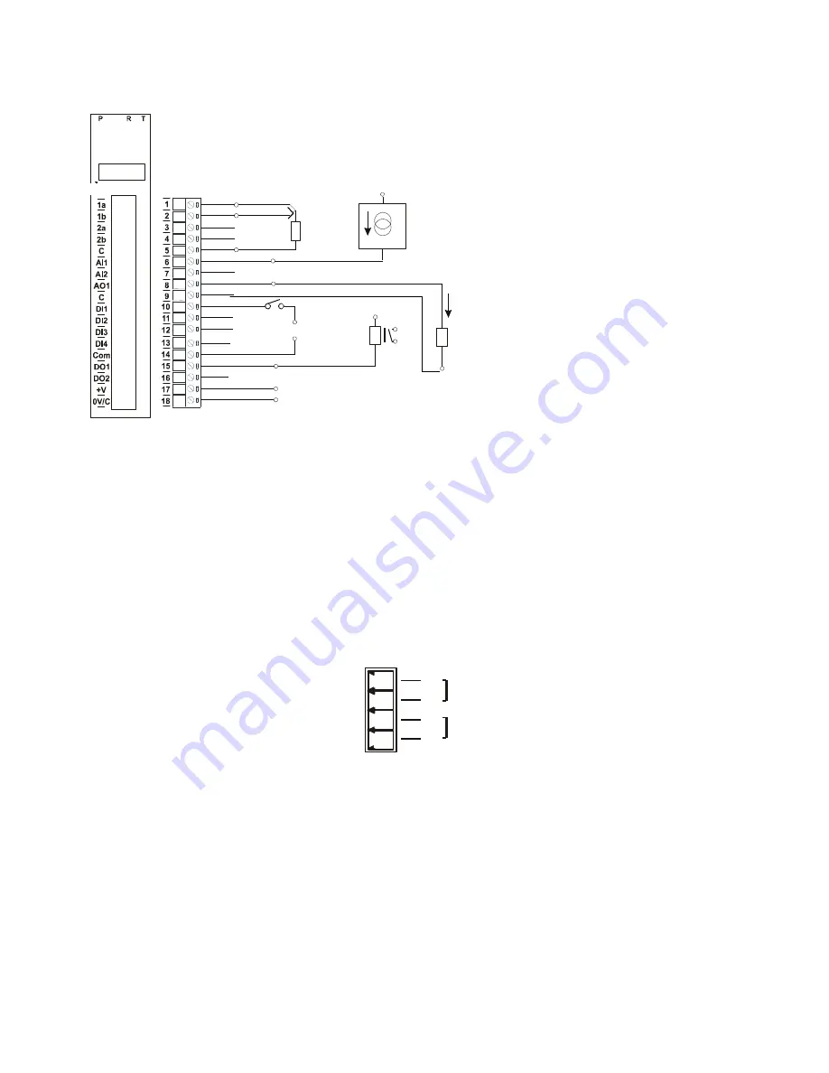
The following diagram shows how the inputs and outputs are connected to the 2300-MULTI station.
Section D: Dip Switch Settings.
DIP SWITCH
FUNCTION
DESCRIPTION
1
STATION ID +1
Station
ID’s from 0 to 127 are set up using switches 1 to 7
2
STATION ID +2
“
3
STATION ID +4
“
4
STATION ID +8
“
5
STATION ID +16
“
6
STATION ID +32
“
7
STATION ID +64
“
8
- Not
used
9
- Not
used
10
BAUD RATE
For MicroScan use DIP Switch 10
ON
(Factory default)
Power and RS485 Comms Wiring.
Warning:
If the power/communication connections are reversed, the remote station may become faulty.
2300-MULTI Station Number Programming and Serial Number.
Important:
When commissioning remote stations, you must programme a unique station number before using the programme
setup button in the Scada Software. Requires MicroScan Version 5.0 onwards.
1.
Close the MicroScan Scada down and turn the power off to the 2300 485 converter. Connect the new Remote
Station, referring to ‘
Wiring and Installation
’ and ‘
Commissioning
’
2.
Turn power back on to the 2300 485 converter, and start MicroScan, under Setup Tools select Add New Station
3.
Select ‘Page and Line Settings’, or ‘Tag Setup’ and configure as per the MicroScan help file.
Important Note:
If using the USB485 converter, do not connect to the computer until after MicroScan has been installed.
MODBUS Applications:
If using the 2300-MULTI station in other applications where
MODBUS
is required, please refer to the
2300-MULTI MODBUS supplementary manual
which is available for download from the Intech website:
www.intech.co.nz/2300
1
3
4
2
- 12Vdc @ 115mA
Pin
Connection
+ 24Vdc @ 58mA
+ Comms
- RS485
70
71
81
82
Notes:
1. Logic power input (terminals 17 & 18) range
12~24Vdc. The logic power supply input must be
isolated and completely separate to the power
supply that powers the 2300-MULTI on terminals 81
& 82. Failure to do so will cause the comms to stop.
2. Terminals 5, 9, 18 are internally connected and
are common for AI, AO RTD and Logic power input.
Terminal 14 DC (Digital Common) is isolated - refer
to Note 5.
3. RTD, AI and DI inputs do not require the Logic
power supply to be connected to terminals 17 & 18.
4. AO1 will only work if the Logic power supply is
connected to terminals 17 & 18. AO will hold its last
value until re-written too.
5. For DI operation, isolation is possible or for non
isolated operation DC (terminal 14) can be
connected to terminal 18 and used with the Logic
power supply. For DO operation the Logic power
supply is required and terminal 14 must be
connected to terminal 18. If using DO and DI,
isolation is not possible.
RTD Input 1a
RTD
1b
Input
RTD Input 2a
RTD
2c
Input
Common/0V
Analog
1
Input
Analog Input 2
Analog Out
1
put
Common/0V
Digital
1
Input
Digital Input 2
Digital
3
Input
Digital Input 4
Digital
Common
Input
Digital Output 1
Digital Output 2
RTD
3 Wire
+V
Common/0V
+24Vdc
0Vdc
+24Vdc
0Vdc
0Vdc
+24Vdc
or
+24Vdc
RELAY
+
-
+24Vdc
+
Two Wire Transmitter
0(4)-20mA
-
Analog Load
0 - 20mA
or
0 - 10V
+
-
0Vdc
2300-MULTI
(Power supply for input logic section)


