background image


- Segment conveyor-page 4.2 

Transport & assembly 

4. 

4. 


4.4 Assembly, electrical and pneumatic connection 

 
The  delivered  segment  conveyor  is  completely  assembled  and  must  only  be  integrated  into  the 
control mechanism of an existing system. Furthermore, electrical power supply must be ensured. 
Installation  of  the  segment  conveyor  using  the  vibration  dampers  is  sufficient.  However,  we 
recommend  a  fixed  installation.  After  disassembly  of  the  vibration  dampers,  eight  M6  threads  for 
fixed installation can be found in the base plate underneath the segment conveyor. 
 
Electrical  connection  and  actuation  via  the  customer-provided  control  takes  places  via  a  25-pin 
SUB D bushing. 
The pneumatic connection takes place via a 8 mm plug coupling. 
The  complete  electronics  and  pneumatics  (valves,  sensors,  etc.)  are  wired  and  with  all  piping  by 
the  manufacturer  in  the  inside  of  the  housing.  For  exact  connection  wiring  of  your  segment 
conveyor refer to the enclosed terminal and PIN diagram. 


In case of malfunctions, the system must be disconnected from the power supply. 


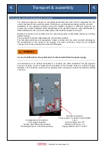
All  connections  are  by  default  connected  to  a  terminal.  For  cable  penetration  into  the  segment 
conveyor  housing,  a  slot  is  located  at  the  backside  of  the  housing.  Ensure  a  sufficient  supply 
diameter.  The  connection  cable  must  be  equipped  with  a  properly  connected  protective  earthing 
conductor. 


WARNING 

Compressed air connection: 

8 mm plug-in coupling 

Quality: dried, filtered and unoiled 

Operating pressure: 6 bar factory setting 

Electrical connection: 

Power supply connection: 25-pin SUB-D 

bush 

Control voltage: 24 V DC 

Nominal current: min. 1 A 

Supply diameter: 25 x 0.14 mm

2


Summary of Contents for SG2H Series

Page 1: ...Operation Manual and Assembly Instructions Segment Conveyor SG Series SG2H SG2L SG3H SG3L...

Page 2: ...pliance or insufficient compliance with the safety criteria indicated in these operation manual and or by modifications to the machine or the use of inadequate spare parts If in doubt the text of the...

Page 3: ...____________________________ 3 2 4 Transport assembly Page 4 1 4 2 4 1 ___Transport information _____________________________ 4 1 4 2 ___Safe installation information ________________________ 4 1 4 3...

Page 4: ...conveyor SG Series SG2H SG2L SG3H SG3L 1 2 Manufacturer service INTEC Automationsprodukte f r Industrietechnik GMBH Werner von Siemens Str 11 D 93128 Regenstauf Phone 49 0 94 02 93 29 0 Fax 49 0 94 0...

Page 5: ...chapter 3 Main components for information regarding the functional design The segment conveyor is intended for integration into a main machine The segment conveyor is not equipped with a control unit...

Page 6: ...use setup maintenance repair It is prohibited to bypass or disable safety and protective equipment Only skilled briefed personnel may perform work on segment conveyor and equipment Operation of the se...

Page 7: ...m component sizes Article number Sorting position Sort items Min part size Max part size Max part length SG2H hanging e g screw approx M 1 6 approx M 5 approx 50 mm SG2L flat e g cylinder pin 2 0 mm 6...

Page 8: ...G3H and SG3L approx 2 0 litre 657 465 430 225 160 534 357 437 200 All data in the tables in chapter 1 5 Dimensions are stated in mm 1 6 Noise level Air borne noise Measuring process in process measure...

Page 9: ...self Furthermore the manager has to guarantee that the staff has entirely understood the contents of this operation manual Only staff members who have specialist proven knowledge are allowed to perfor...

Page 10: ...untries The employees must be instructed with regard to risks and the necessary protective measures at regular intervals at least however once per year The carrier of the segment conveyor must prepare...

Page 11: ...ng Do not reach with your hands into the parts separator The segment conveyor may not be operated without sufficient safeguarding of the lifting segment Separator or deflector The carrier of the segme...

Page 12: ...l Using deflectors the parts can be specifically distributed from a segment conveyor to up to four processing machines The deflectors are mechanically separated from the segment conveyor and thus have...

Page 13: ...ntainer with lifting segment which executed controlled raising and lowering movements When raised the lifting element picks several product parts in the correct position up In the upper end position t...

Page 14: ...ed persons prior to performing setup work on the segment conveyor Mount warning and information signs clearly visible prior to work start Only use proper tools especially spanners which do fit and are...

Page 15: ...a 8 mm plug coupling The complete electronics and pneumatics valves sensors etc are wired and with all piping by the manufacturer in the inside of the housing For exact connection wiring of your segme...

Page 16: ...ssed Prior to shift start briefed and trained personnel must check safety and protective devices for proper condition If deficiencies are detected which impact the safety of the segment conveyor the s...

Page 17: ...on of the segment speed The segment movement control valves are easily accessible at the back of the unit Hence segment speed should always be adjusted using the exhaust throttle Too high segment spee...

Page 18: ...quency may vary depending on used product parts and must be practically determined Monthly Check transitions between segment and feeding rail and between feeding rail and separator for offsets or gaps...

Page 19: ...trically and pneumatically isolated 6 3 1 Clean parts container Carefully remove screws by hand from the parts container Remove coarse dirt using a vacuum cleaner Remove wax and other wear from the pa...

Page 20: ...page 6 3 Maintenance setting 6 6 6 3 2 Lifting segment cleaning Do not bend rejection springs CAUTION a Remove wax and other wear from the lifting segment using a cloth and some solvent b Carefully c...

Page 21: ...3 3 Sorting channel cleaning Do not bend rejection springs CAUTION a Remove contaminations from the segment gap within the sorting channel using a Q tip and some solvent b Remove contaminations withi...

Page 22: ...3 4 Output rail cleaning Do not bend hold down clamps or upstream separator Do not damage optical fibres and sensor system CAUTION a Remove contaminations from the slide surfaces of the output rail an...

Page 23: ...ould take occur at least once a week Once per shift the slide surfaces from segment to separator should be roughly cleaned It is sufficient to clean the slide surfaces from depositions using a cloth s...

Page 24: ...al Operating Equipment 2006 95 EC and Electromagnetic Compatibility 2004 108 EC The incomplete machine may only be commissioned after determination that the machine in which the incomplete machine sho...

Reviews: