


TriggerLinc Owner’s Manual
Page 5 of 12
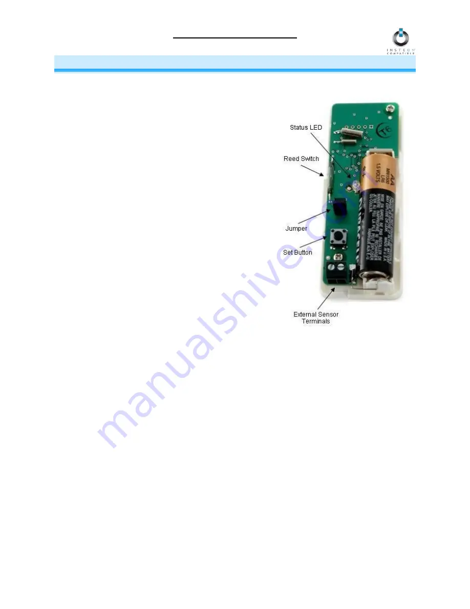
INSTALLATION
TriggerLinc Hardware
Reed Switch
Used by TriggerLinc to detect whether the included magnet is
within ½ inch of the main case:
Reed switch is in the closed state when the magnet is
inside ½ inch
Reed switch is in the opened state when the magnet is
further than ½ inch
Jumper
When the jumper is installed (default), TriggerLinc will send an
INSTEON ON command when it opens and an OFF command
when it closes. When the jumper is uninstalled (as in Multi-
Scene Mode), TriggerLinc will activate Scene 1 when it opens
and activate Scene 2 when it closes.
NOTE: When installing or uninstalling the jumper, the battery will
need to be removed and then reinstalled for the new jumper
setting to take effect.
Set Button
Used to:
Link to other INSTEON devices (Responders)
Control Linked Responders (Scene 1): tap to toggle
between on and off
External Sensor Terminals
When using an external sensor, TriggerLinc is in the closed state when
either
the external sensor
terminals or the reed switch are closed. In other words, TriggerLinc opens when
both
the external sensor
terminals and reed switch are open. See
Advanced Use of External Sensors with TriggerLinc
for more
information.
Status LED
Indicates:
Change in state (opens or closes)
TriggerLinc is in Linking/Unlinking Mode (Status LED is blinking)
Arrows
Arrows indicate the location of the reed switch inside the main case, so the magnet should be installed as
close as to them as possible.
Magnet
Included magnet is installed on opposing plane than TriggerLinc main case. It should be less than ½ inch
away from the main case when the door/window, etc. is closed and further than ½ inch when open.
(Antenna not
shown for clarity)


