background image


Battery Charging Instructions 


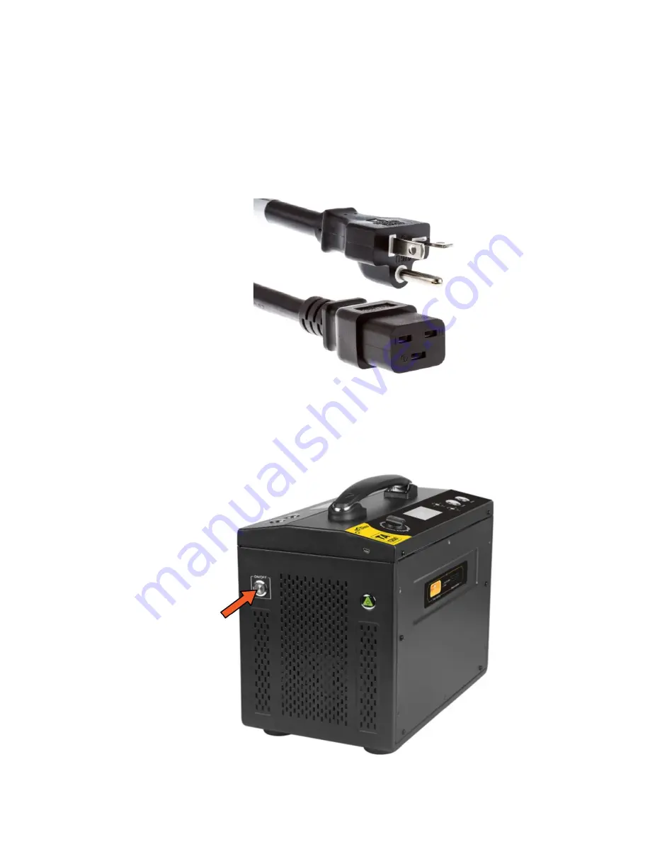
Plug in the charger unit using the power cable included. Make sure the charger is 
plugged into a 110v power source. 


Press the power button on the side of the battery charger to power on the unit. 
Fans will begin spinning, and the LCD screen on each side of the charger will 
illuminate. 


Summary of Contents for IF1200

Page 1: ...IF1200 Hexacopter User Manual...

Page 2: ...Propellers 17 Powering On Vehicle 20 Powering On Controller 21 Flight Modes 21 Altitude Mode 21 Position Mode 21 Return to Home Mode 22 Kill Switch 22 Opening QGroundControl 24 Arming and Takeoff 25...

Page 3: ...1 Product Profile 1 1 Aircraft Overview Each IF1200 comes bound and ready to fly Listed below are all the various subassemblies included in the kit 3...

Page 4: ...1 2 Controller Overview Jeti DS 12 Controller Note Switches not labelled are not programmed for standard use but can be customized to conduct any Mavlink commands 4...

Page 5: ...Herelink Controller Note Switches labeled as Disabled are not programmed for standard use but can be customized to conduct any Mavlink commands 5...

Page 6: ...2 Flight Instructions 2 1 Tattu TA1200 Battery Charger 6...

Page 7: ...sing the power cable included Make sure the charger is plugged into a 110v power source Press the power button on the side of the battery charger to power on the unit Fans will begin spinning and the...

Page 8: ...ard and Fast If time is not an issue it is recommended to charge the batteries as slowly as possible for extended battery health Uncap the battery and plug into one side of the charger Note The connec...

Page 9: ...cells while charging first connect each end of the balance cable into the corresponding balance ports on the battery and charger Follow the charging instructions above to conduct a balanced charge Sto...

Page 10: ...The Inspired Flight UAV will automatically connect to QGC once the vehicle has been powered on and the USB telemetry module included has been plugged into the PC or Tablet If using a Herelink Controll...

Page 11: ...es on the end inserts should line up perpendicularly to the horizontal tube Ensure the vertical tube is fully seated before tightening the ratcheting clamp If there are o rings on the vertical tube in...

Page 12: ...t steps are most easily done with two people one person holding body one assembling Lift the GPS mast into place latching the clips on both sides Unfold the six aircraft arms into upright position The...

Page 13: ...to the corresponding sockets on the underside of the vehicle Again ensure the vertical tube is fully seated before tightening the ratcheting clamp The ratcheting arm can be pulled away from the screw...

Page 14: ...1 The battery is oriented such that the battery s indicator lights and cables are at the rear of the vehicle 2 The battery is centered left and right Note While centering it helps to look at the batt...

Page 15: ...he battery The plastic loop should be close to the center of the battery Pull the straps tightly over the battery securing the velcro strap to itself close to the body of the vehicle Note While tighte...

Page 16: ...aircraft Note The connector design ensures a mistake can not be made with the connector orientation Ensure the connectors are pushed together fully Gently grab the battery and attempt to move it in pl...

Page 17: ...ockwise and three will spin counterclockwise The two motor and prop types have keyed quick disconnects that prevent a user from mounting the wrong propeller on the wrong motor The clockwise quick disc...

Page 18: ...the aluminum quick disconnect resting on the motor itself Tighten the propellers onto the motors ensuring not to over tighten We recommend using the provided green handled screwdriver Tighten each re...

Page 19: ...When the propellers are mounted correctly the propellers should be parallel to the top surface of the motor and everything should be fully seated and firmly secured 19...

Page 20: ...le for 5 seconds The LED indicator light will turn green when the aircraft is on and beeping will occur during the initialization sequence The LED on the GPS mast will begin breathing blue as it searc...

Page 21: ...ding Altitude Mode In Altitude mode the IF1200 will maintain its vertical position with the left stick centered and the left stick controls altitude of the drone The right stick controls pitch and rol...

Page 22: ...r keep an eye on the battery level in QGC and replace the batteries conservatively to mitigate risk This mode is recommended for normal landings and for landing after an autonomous mission Kill Switch...

Page 23: ...the computer 3 Double click the QGroundControl icon on the desktop or open the QGC tablet app 4 With the drone powered on QGroundControl will automatically connect to the vehicle For more information...

Page 24: ...ssion 4 Fly Monitors the vehicle during operation providing telemetry readouts and any video streaming overlay This screen can toggle between a map view of the vehicle currently flying and video strea...

Page 25: ...flight controller has obtained a suitable GPS signal It will also automatically enter position flight mode when this happens 2 Arm the drone by holding the left stick on the radio down and to the righ...

Page 26: ...s level and clear of obstructions If it is dangerous to land in the home position flipping the flight mode to Position Mode before the drone has landed will give full control to the pilot The aircraft...

Page 27: ...s the Fly view with a simple mission plan that starts with a takeoff at the Planned Home position P flies through three waypoints and then lands on the last waypoint i e waypoint 3 The main elements o...

Page 28: ...3 Upload the mission to the vehicle 4 Change to Fly View and fly the mission Further details are explained below Note If flying in an autonomous mode and mission return is behaving unexpectedly danger...

Page 29: ...nce you have added a waypoint you can select it and drag it around to change its position File Sync The File tools are used to move missions between the ground station and vehicle and to save restore...

Page 30: ...individual mission items to edit their values Mission Settings The Mission Start panel is the first item that appears in the mission command list It may be used to specify a number default settings th...

Page 31: ...me Position The Planned Home Position section allows you to simulate the vehicle s home position while planning a mission This allows you to view the waypoint trajectory for your vehicle from takeoff...

Page 32: ...not connected to the IF1200 The additional value that can be specified when planning a mission is the vehicle flight speed By specifying this value total mission or survey times will be approximated e...

Page 33: ...e printed and stuck to the top carbon plate where the battery is mounted 3 2 Calibrating the Compass When the drone is transferred between areas more than 300 miles it could be necessary to recalibrat...

Page 34: ...conds in each of the orientations shown Green boxes show complete orientations the yellow box shows current calibrating orientation and red boxes indicate incomplete orientations 1 Hold the drone stea...

Page 35: ...dly dangerously or abnormally switch to position mode to regain control If flying in manual position control and flight becomes unstable unpredictable or dangerous determine if killing the motors enti...

Reviews: