INOXPA PHARMAVALVE Installation, Service & Maintenance Manual Download Page 3


ED. 2009/09 / 


1.


Safety 

1.1. 


INSTRUCTION MANUAL 

This manual contains basic instructions which should be fulfilled during the installation, starting and maintenance.  
The contents published in the instruction manual is based on updated information. 
INOXPA reserves the right to modify this instruction manual without prior notice.


1.2. 


START-UP INSTRUCTIONS 

This instruction manual contains vital and useful information to correctly handle and maintain your valve. 
Not only should the safety instructions indicated in this chapter be observed and fulfilled, but so should the special measures 
and recommendations included in the other chapters of this manual. These instructions should be kept in a safe location near 
the installation. 

 
1.3. 


SAFETY 

1.3.1.  


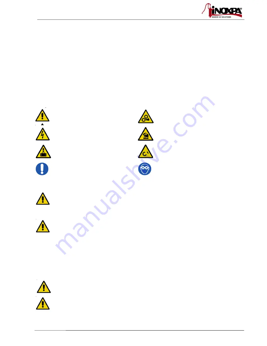
Warning symbols. 


Danger for persons in general 


Danger of injury caused by rotating 
equipment parts. 


Electrical danger 


Danger! Caustic or corrosive agents. 


Danger! Suspended loads 


Danger to the correct operation of the 
equipment. 


Commitment to safety at the workplace. 


Protective goggles requirement. 


1.4. 


GENERAL SAFETY INSTRUCTIONS 


Read the instruction manual carefully before installing and starting up the valve. Contact INOXPA in 
case of doubt. 


1.4.1.  


During the installation. 


The 

Technical Specifications

 of Chapter 8 should always be observed.


The installation and use of the valve should always be carried out in accordance with applicable 
regulations regarding health and safety. 


Before starting up the valve, confirm that the assembly is correct and that the shaft is perfectly 
aligned. Incorrect alignment and/or excessive force in securing the valve may cause serious 
mechanical problems in the valve. Check that the diaphragm has been correctly assembled, as 
incorrect assembly may cause serious damage to the valve. 


1.4.2.  


During operation. 


The 

Technical Specifications

 of Chapter 8 should always be observed. Never exceed the specified limits. 


NEVER touch the valve and/or pipes that are in contact with the liquid during operation. If working 
with hot fluids, there is a risk of burns. 


Summary of Contents for PHARMAVALVE

Page 1: ...VIC STRUC ARMAV INOXPA lers 54 A 17820 Ba Girona S 34 972 34 972 inoxpa www inoxp E AND CTIONS AVALVE S A Aptdo 17 anyoles Spain 57 52 0 57 55 0 inoxpa co pa com ORIGI D MAIN S E 4 00 02 om INAL MAN N...

Page 2: ...actice determined according to Article 3 Section 1 3 a first paragraph annex II table 6 This material should not have the CE marking Diameter DN 25 X or DN 100 Equipment category Category I determined...

Page 3: ...loads Danger to the correct operation of the equipment Commitment to safety at the workplace Protective goggles requirement 1 4 GENERAL SAFETY INSTRUCTIONS Read the instruction manual carefully befor...

Page 4: ...1 5 GUARANTEE Any guarantee will be negated immediately and as a matter of law and in addition we will require compensation for any claims of civil liability presented by third parties in the instanc...

Page 5: ...cation 8 3 6 Flow direction 8 3 7 Assembly 8 3 8 Inspecting and checking 9 3 9 Welding 9 3 10 Air connection to actuator 10 4 Start up 4 1 Start up 11 4 2 Operation 11 5 Operating problems Causes and...

Page 6: ...from the valve or parts Inspect the valve or its constituent parts for possible damage caused during transport Avoid any possible damage to the valve and its components 3 3 STORAGE If the valve and or...

Page 7: ...ATIC 5 TANK BOTTOM NO PNEUMATIC 6 A A PNEUMATIC 7 TANK BOTTOM A A PNEUMATIC CASING DESIGN 0 L CASING O D ASME 1 T CASING O D ASME 2 45o OUTLET O D ASME CASING MATERIAL 06 AISI 316L DIAPHRAGM MATERIAL...

Page 8: ...rection of closure In T type bodies the normal direction is shown in figure c as it minimises pressure losses and dead zones T type casings are NOT 3 way valves they act as a divider when the valve is...

Page 9: ...lding work can only be carried out by persons qualified trained and equipped with the necessary means to carry out this work Disassemble the valve before starting the welding work 3 9 1 PHARMAVALVE Bu...

Page 10: ...low intensity High intensity may deform the valve Continue welding until the body is completely welded Leave to cool gradually Cool by air only Turn over the tank base and weld from the inside Leave...

Page 11: ...e Chapter 8 Technical Specifications Bear in mind the quality of the compressed air in accordance with the specifications described in chapter 8 Technical Specifications Operate the valve 4 2 OPERATIO...

Page 12: ...ibration Replace the diaphragm with one of a different material and more appropriate to the product Tighten any loose components Clean frequently In actuators NO and A A reduce the air pressure Backpr...

Page 13: ...g maintenance Danger of burns 6 2 1 Diaphragm Maintenance REPLACING THE DIAPHRAGM Preventive maintenance Replace after twelve 12 months In general the diaphragm must be inspected every 50 hours of ste...

Page 14: ...at 70 C 150 F 1 Kg NaOH 100 l of water cleaning solution or 2 2 l NaOH at 33 100 l of water cleaning solution b Acid solution 0 5 by weight of nitric acid HNO3 at 70 C 150 F 0 7 litres HNO3 at 53 100...

Page 15: ...ft as appropriate for type A or B 2 Place the actuator 10 in the open valve position Connect the body 01 to the actuator 10 using the clamp 34 The type A diaphragm press on is standard for Silicone an...

Page 16: ...he actuator 10 in order to set the diaphragm 05 in the open position NC valve only Connect the body 01 to the actuator 10 by tightening the clamp 34 Disconnect the compressed air from the actuator 1 s...

Page 17: ...h DIN ISO 8573 1 o Solid particle content Class 3 quality Max particle size 5 microns Max particle density 5 mg m3 o Water content Class 4 quality max dew point 2 o C If the valve is operating at high...

Page 18: ...18 ED 2009 09 8 1 VALVE DIMENSIONS 10 310 32 0010...

Page 19: ...eumatic Actuator H 42 77 5 94 5 I 60 69 90 Bodies J TC50 5 TC77 5 TC77 5 k 82 124 124 L 41 62 62 M 19 5 32 37 5 N 36 5 61 2 67 2 O 50 79 100 P 47 104 120 Q 28 5 52 R 60 95 5 121 7 T 94 208 240 U 35 67...

Page 20: ...1 01B Nut support AISI 316L 1 04 Handle AISI 316 1 05 Diaphragm 1 08 Diaphragm shaft AISI 316 1 17A Support bushing AISI 316 1 17B Guide bushing PTFE 1 17I Bearing bushing AISI 316 1 20B O ring FPM 1...

Page 21: ...06 Spring AISI 302 5 08 Piston shaft AISI 316L 1 08A Diaphragm shaft AISI 316L 1 11 Spring guide POM 1 17 Guide bushing PTFE 1 18C R 1 8 straight connector 1 18D R 1 8 Silencer 1 20A O ring FPM 1 20F...

Page 22: ...NOTES...

Page 23: ...NOT TES...

Page 24: ...X GLEIZE BASSE GOULAINE WAMBRECHIES Tel 33 474627100 Tel 33 228010172 Tel 33 320631000 Fax 33 474627101 Fax 33 228010173 Fax 33 320631001 e mail inoxpa fr inoxpa com e mail inoxpa fr inoxpa com e mail...

Reviews: