background image

 21 

for every dial location that carries the program.  Always include the

main transmitter frequency, otherwise the RDS radio will not switch

back when required.  A button below the Alternative Frequencies

box allows all checks to be cleared at once.

TRAFFIC ALERTS

The TP / TA function is a useful provision of the RadioData System,

but one with a potential for abuse.  TP / TA is detailed on Page 10,

including an explanation of how the utility can be abused and the

safeguards built into the Model 720 to prevent this.
In order for a station to air TA (Traffic Alert) messages, it must first

be listed as a TP (Traffic Program) station; that is, a station that

routinely includes traffic updates in the normal programming

schedule.  RDS radios keep track of TP stations and  look  for a TA

flag only from among those stations.
If your station does air

routine traffic announce-

ments, check the

TP

 box.

This will then permit the

encoder to send TA flags

on demand.
In keeping with RDS and RBDS regulations, the TA flag is to be

sent only for critical traffic-related announcements, and then only

for the actual duration of the accompanying voice message.  We rec-

ommend using only the direct-connected, hardware-switch-activa-

tion of the TA flag described on Page 32.  However, as the encoder

may be installed some distance from the studio and addressed by a

serial (or modem) connection, provision has been made to set the TA

flag with a software command.
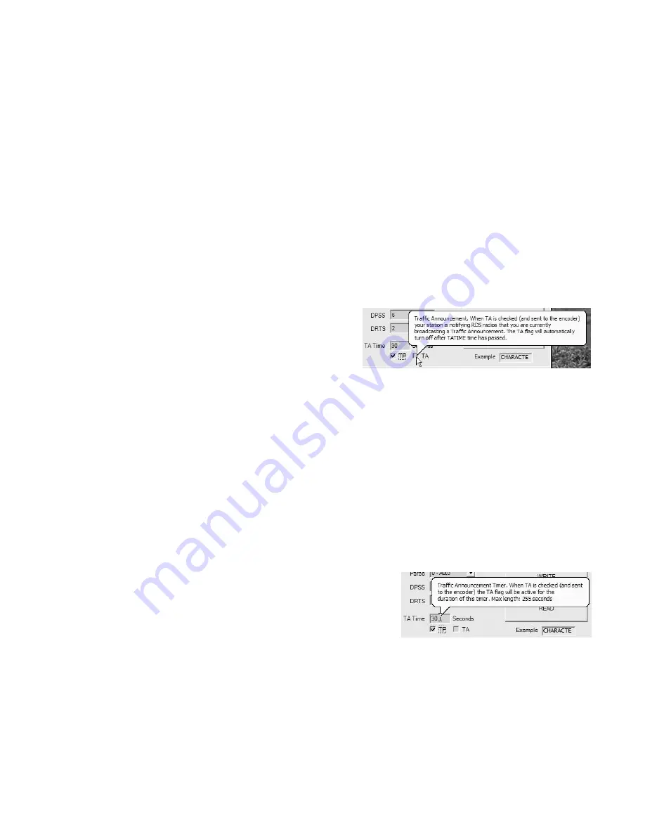
Nevertheless, the

TA

 box on the 720 software screen may be checked

to initiate a TA flag.  The flag is then transmitted immediately when

the

WRITE

 button is clicked.  To clear the flag when the announce-

ment is finished, uncheck the TA box and click

WRITE

 once again.

TA Time

The 720 is equipped with a built-

in timer that limits the maximum

period for TA-flag transmission.

This guards against a short-

circuit in a hardwired TA instal-

lation, or in the event that a second software command is not re-

ceived at the end the TA announcement.  TA may be set to time out

after a period of up to 255 seconds, with the 30-second factory-

default value a typical setting.  The TA timeout is set in the TA

Time box, and a Help balloon gives additional hints.

Once the TA has timed-out, the TA function resets and has to be re-

initiated to proceed with another announcement.

Summary of Contents for 720

Page 1: ...PROGRAMMING AND OPERATION INSTRUCTION MANUAL MODEL 720 R D S RADIO DATA SYSTEM RADIODATA ENCODER ...

Page 2: ......

Page 3: ...___________ Warranty Card Mailed o PROGRAMMING AND OPERATION INSTRUCTION MANUAL MODEL 720 R D S RADIO DATA SYSTEM RADIODATA ENCODER Rev 1 February 2008 Initial Release 1305 Fair Avenue Santa Cruz CA 95060 TEL 831 458 0552 FAX 831 458 0554 Visit our Website www inovon com ...

Page 4: ......

Page 5: ... PTY RAW RT TA TP COMMUNICATING WITH THE MODEL 720 ENCODER 10 Section III SOFTWARE INSTALLATION AND FIRMWARE SETUP INSTALLING THE SOFTWARE 12 Install Software First Microsoft dot NET Framework Installing the USB Driver RUNNING THE SOFTWARE 13 Data Entry THE MENU BAR 14 RDS RBDS Station Type the M S Switch Txmtr Type the DI Switch Header The Help Menu PI AND PTY CODES 16 PI Code and the Calculator ...

Page 6: ...MANDS 27 Register Interrogation Encoder Initialization Saving to Non Volatile Memory Encoder Reset Firmware Version Communication Speed Section IV ENCODER INSTALLATION MOUNTING 28 Rack Requirements Heat Dissipation AC MAINS POWER 28 Fuseholder Mains Voltage Selector Power Cord RADIO FREQUENCY INTERFERENCE RFI 29 Location Ground Loops SELECTION OF OPERATING MODES 29 Sidechain Mode Loop Through Mode...

Page 7: ...SCRIPTIONS INTRODUCTION 37 Component Annotation Stereo Pilot Recovery RDS Waveform Synthesis Band Pass Filter RDS Signal Combining and Output Stage Encoder Data Formatting Power Supply Section VII APPENDIX ENCODER COMMANDS AND PROMPTS 40 US AND EUROPEAN PTY LISTINGS 41 ALTERNATIVE FREQUENCY CHANNEL NUMBERS 42 COMPONENT PARTS LIST 43 PARTS SUPPLIERS 44 SCHEMATIC DIAGRAMS 46 INOVONICS WARRANTY INSID...

Page 8: ...cs and safeguards of fered for the first time in the Model 720 allow for near foolproof RDS implementation at any FM radio station Every step has been taken to guarantee simple straightforward and safe operation Features Leading features of the Inovonics 720 include Front panel LCD screen and built in diagnostics both in en coder firmware and software Static data quickly programmed or updated with...

Page 9: ...anced 75 ohm BNC out put to feed a wideband input of the FM exciter RDS Injection Level Subcarrier level is continuously ad justable from the front panel from zero to 3V p p The LCD screen gives both bargraph and voltage readouts Serial Data Port A rear panel RS 232 port DB9 ac cepts static encoder programming and dynamic messaging from sta tion automation The 720 accom modates all common data rat...

Page 10: ...mes necessary If returned for Warranty repair shipping damage sustained as a re sult of improper packing for return may invalidate the Warranty IT IS IMPORTANT to complete and return the War ranty Registration Card that accompanies this manual or the Warranty registered on the Company s Website www inovon com This assures coverage of the equip ment under terms of the Warranty provides a means of t...

Page 11: ... Inovonics Model 720 Encoder In particular the explanations of the various messaging and house keeping functions afforded by RDS will help the reader become more familiar with what the system has to offer and how it can be used to the broadcaster s greatest advantage These explanations begin on Page 8 RDS EUROPE vs AMERICA The European Broadcasting Union EBU and its member countries originated the...

Page 12: ... RBDS to differentiate it from its European counterpart Differences between the two standards have been reconciled and minimized over the years yet RBDS prevails as the US designation For the sake of clarity and simplicity the more generic and established term RDS will be used throughout this Manual RDS APPLICATIONS SUPPORTED BY THE MODEL 720 The following is an alphabetical listing of RDS applica...

Page 13: ...ven on automobile receivers so it was meant to remain static Because of driving safety considerations broadcasters have from the start been discouraged from making the PS dynamic that is to send long messages in a succession of 8 character frames As a matter of note it remains a violation of both the CENELEC and the NRSC standards to flash or scroll the PS display Nevertheless this nefarious pract...

Page 14: ... to receive it When the bulletin is finished the receiver switches back to the original program CD or MP3 The takeover nature of the TA function has spawned numerous abuses mostly in a misguided and evil attempt to steal listeners A naughty broadcaster might tease a listener he has just grabbed by mentioning some hot pop star interview that s up next on his station as he goes into his traffic upda...

Page 15: ...Local Area Network or the Internet Inovonics does offer RDS encoders that do provide a direct network connection However a third party IP to serial converter functioning as a telnet server may be used with the 720 to offer TCP IP connectivity Early RDS deployment in Europe included a provision to link RDS encoders with one another for network support applications The UECP or Universal Encoder Comm...

Page 16: ... Software should be installed on the computer before the computer is connected to the 720 Encoder The same software is used for either USB or serial connection between the computer and the Model 720 Microsoft dot NET Framework 720 software utilizes components of Microsoft s dot NET frame work This utility has been distributed through routine Microsoft XP updates and should be resident on any well ...

Page 17: ...hen click Next Continue to click Next until installation reaches the window shown on the right Highlight the driver on the CD ROM drive named C Program Files Inovonics RDS Encoder 720 USB Drivers as shown and then click Next once again When driver installation completes the final screen will prompt you to click Finish At this point you will see an other notification this time advising that the new...

Page 18: ... the top of the window This brings down a sub menu that allows the user to save programming setups from the encoder to a small file on the computer or to load setups from a file on the computer to the encoder Files will be assigned a rds extension The 720 file utility is useful for distributing a common encoder setup among stations in a network or for easily changing non dynamic scrolling PS or Ra...

Page 19: ... included in the CENELEC specification Header An important feature of the 720 and one that sets it apart from ear lier models and most competitive products is the ability to transmit scrolling PS messages from raw unformatted ASCII text In the preferred mode of operation scrolling PS messages are preceded by the special header DPS This prepares the encoder to format and send the following text str...

Page 20: ... code is essential to proper RDS system operation RDS radios may actually tune away from a station transmitting RDS data groups that do not include a valid PI code When the Model 720 is operated in the European RDS mode the 4 character hexadecimal PI code is typed directly into the PI box Note that the box marked Call is grayed out in the RDS mode In the US and Canada however the PI code is derive...

Page 21: ...emi dynamic function in that it is permitted to change from one format category to another if the sta tion dayparts or alters formats during specific extended segments of the broadcast day The PTY should not change from song to song or to accommodate a 5 minute newscast NOTE The PTY codes relating to emergencies are reserved for true emergency and emergency test situations only Consult the appro p...

Page 22: ... of the scrolling PS message but some radios cannot keep up with a really fast scroll We recommend a as a top scrolling speed The field will now be open for data entry Hovering over the DPS field will pop up a Help balloon with hints and reminders Place your cursor in the box clear what s there and type in your text The character counter to the right of the field shows the number of characters ent...

Page 23: ...lp balloon with this same in formation Safe Scrolling We developed Safe Scrolling because of our concern over distracted automobile drivers When viewing a message composed of complete words or groups of words a driver must pay close attention to the radio display or risk missing part of the message Although the message may be repeated over and over the driver may tune in at the end of a song and i...

Page 24: ...smitted Because Radio Text is a static message generally relegated to secondary information the refresh rate does not need to be very high On the DRTS Dynamic Radio Text Speed scale of 1 to 9 a setting of 2 or 3 is usually quite adequate Keep in mind that with a faster re fresh rate Radio Text will monopolize transmission resources and compromise the speed of scrolling PS messaging The DRTS drop d...

Page 25: ...elated announcements and then only for the actual duration of the accompanying voice message We rec ommend using only the direct connected hardware switch activa tion of the TA flag described on Page 32 However as the encoder may be installed some distance from the studio and addressed by a serial or modem connection provision has been made to set the TA flag with a software command Nevertheless t...

Page 26: ...nnect the USB cable from the encoder Using the DB9 serial cable provided connect the computer to the Model 720 In the Menu Bar click Interface and then RS 232 This will bring up a box labeled RS232 Settings In this box the baud rate of the com puter and encoder ports may be set manually using drop down menus or a handy built in utility will automatically determine set tings Changing Baud Rates Whe...

Page 27: ...tion or a terminal discussed next THE SOFTWARE TERMINAL UTILITY With a 2 way serial connection between the computer and encoder first check that the encoder is set to the normal header mode In the Menu Bar click Format and hover over Header See that Yes Nor mal Operation is checked Next click Interface and then RS 232 to reopen the RS232 Settings box Click Terminal to bring up the data entry box s...

Page 28: ...text but each character will be seen as it is en tered When the Enter key is pressed after the text has been typed in the reply OK indicates that data has been received and saved in encoder RAM Note that the answerback response is always a cou ple of lines below the entry The terminal utility is not intended for use as a text editor in that typing errors are not easily corrected in this window If ...

Page 29: ...ng using the Windows software is automatically followed by a SAVE8 command that transfers it to non volatile encoder memory This further empha sizes the desirability of using 720 software for setting the various RDS registers to protect their contents Losing dynamic data should not be a worry however as the only messaging with headers generally streamed to the encoder is scroll ing PS song titles ...

Page 30: ...hat comes up in the terminal utility window is actually coming back from the encoder With one way transmission text or commands typed into the terminal win dow will not be visible but will nevertheless be sent to the encoder Again use of the supplied software requires a 2 way link THE FREE FORMAT GROUPS Under the RDS and RBDS Standards the RadioData system is able to transmit unspecified data grou...

Page 31: ...Win dows software to save an rds file see Page 22 Saving to Non Volatile Memory RDS parameters are transferred from RAM to non volatile EEPROM with a SAVE8 command This is done automatically when using the supplied Windows software Encoder Reset Typing RESET8 performs a soft restart equivalent to powering the encoder down and back up again This reset command does not clear the registers of program...

Page 32: ...eversing the removal process This fuse also serves as a front panel emergency power disconnect for the Model 720 Mains Voltage Selector Unless specifically ordered for export shipment the 720 is set at the factory for operation from 115V 50 60Hz AC mains This can be confirmed by checking the designation next to the mains connector on the rear panel The inappropriate voltage and fuse value will hav...

Page 33: ...l to derive timing information from the 19kHz stereo pilot Alternatively a TTL level 19kHz sync squarewave may be applied to this input We do not recommend this however because of possible phase ambiguities between the synchronizing squarewave and the 19kHz pilot component in the composite multiplex output of the stereo generator In sidechain operation the encoder s RDS OR MPX OUTPUT will con tain...

Page 34: ...the composite MPX output of the stereo generator connect one side of the directly to a wideband com posite MPX input of the FM exciter and the other side to the PILOT OR MPX INPUT of the Model 720 as shown in Figure 3 This is only a bridging sync connection with the circuit board jumpered for sidechain operation and does not affect the composite MPX signal Using a Separate Sync Source If the stere...

Page 35: ...MPX signal passes through the encoder with unity gain with the RDS subcarrier added or routed directly through the encoder by the bypass relay in the event of encoder power loss Figure 4 Loop Through Encoder Connection FM STEREO GENERATOR PROGRAM LINE IN MPX OUT FM EXCITER 1 2 3 WIDEBAND INPUTS RF OUTPUT MODEL 720 ENCODER PILOT OR RDS OR MPX RS 232 LOCAL MPX INPUT OUTPUT COM PORT TA CONTROL FM STE...

Page 36: ...uration of a traffic announcement The TA flag should be turned off immedi ately after completing the verbal traffic warning which should be automatic if a spring return switch is used The 720 does incorporate a down counting TA timer to prevent a continuous switch closure from signaling a permanent TA flag This timer is user programmed for a specified time in seconds after which the TA flag is aut...

Page 37: ...S 232 interface A cable like the one depicted can be made easily and will work just as well as a serial extension cord with all nine conduc tors connected Computer or Terminal Requirements Although the supplied Windows software and front panel USB port afford the easiest method of entering static RDS data the encoder may also be addressed serially using the terminal emulation pro gram that is part...

Page 38: ...puter or auto mation and the encoder and to read the commands to check that they are valid When incoming commands are sent using the supplied software the contents of all registers are updated whether or not changes have been made Incoming pro gramming will include spaces and carriage returns or 8 symbols necessary parts of the text strings 03 DPS displays the contents of the scrolling PS buffer 0...

Page 39: ...er is the only signal that appears at the rear panel RDS OR MPX OUTPUT connec tor Because some exciters require a high signal level at auxiliary wideband SCA inputs the RDS signal has been made adjustable to any value between zero and 3 volts peak to peak In loop through operation of the encoder the composite MPX pro gram signal that is fed to the PILOT OR MPX INPUT appears with unity gain at the ...

Page 40: ...is matter Subcarrier Phase According to the RDS and RDBS Specifications the 57kHz RDS subcarrier may be either in phase or in quadrature with the 19kHz stereo pilot Both phase relationships are shown in Figures 6 and 7 respectively Note that the quadrature relationship in Figure 7 yields a slightly lower peak level which suggests the possibility of marginally greater carrier modulation by the prog...

Page 41: ...Hz stereo pilot Trimmer adjustment R49 is used to fine tune the phase of the recovered pilot signal PLL IC10 lends further filtering action and squares up the 19kHz waveform as well as pro viding logic to indicate pilot lock IC11 is a second PLL that includes frequency divider IC12 in its loop The output of IC11 is a 114kHz squarewave a six times mul tiplication of the stereo pilot This is a clock...

Page 42: ...ear panel PILOT OR MPX INPUT con nector is passed through this stage at unity gain and will appear combined with the RDS subcarrier at the output Relay K1 provides a failsafe bypass path for the composite MPX signal in the loop through operating mode if encoder power is lost Encoder Data Formatting IC13 is a second PIC microprocessor that is responsible for receiv ing and formatting all incoming R...

Page 43: ...39 Section VII APPENDIX This section of the Model 720 Manual con tains Certain Tabulated Items Parts Listings Schematic Diagrams and an explanation of Inovonics Most Generous Warranty Policy ...

Page 44: ...Fre quency in MHz may also be entered directly Decoder Information DI 0 Mono 1 Stereo M S MS 0 Speech Only 1 Music Radio Text TEXT 64 max ASCII characters Dynamic Radio Text Speed DRTS 0 Radio Text off 1 slow to 9 fast RS 232 Serial Baud Rate SPEED 1200 2400 4800 9600 19200 38400 57600 115200 COMMAND SPECIAL COMMANDS Following a header returns status of encoder memory for that specific parameter e...

Page 45: ...tening Music 13 Nostalgia Music Light Classics Music 14 Jazz Serious Classics Music 15 Classical Music Other Music 16 Rhythm and Blues Music Weather 17 Soft R and B Music Finance 18 Foreign Language Children s Programs 19 Religious Music Social Affairs 20 Religious Talk Religion 21 Personality Phone In 22 Public Non Commercial Travel 23 College Leisure 24 unassigned Jazz Music 25 unassigned Countr...

Page 46: ...8 23 94 9 74 100 0 125 105 1 176 89 9 24 95 0 75 100 1 126 105 2 177 90 0 25 95 1 76 100 2 127 105 3 178 90 1 26 95 2 77 100 3 128 105 4 179 90 2 27 95 3 78 100 4 129 105 5 180 90 3 28 95 4 79 100 5 130 105 6 181 90 4 29 95 5 80 100 6 131 105 7 182 90 5 30 95 6 81 100 7 132 105 8 183 90 6 31 95 7 82 100 8 133 105 9 184 90 7 32 95 8 83 100 9 134 106 0 185 90 8 33 95 9 84 101 0 135 106 1 186 90 9 34...

Page 47: ...ice surprise C1 2 Capacitor Y class Ceramic Disc 0047µF 440VAC Mu rata Erie DE7150 F 472M VA1 KC C3 4 Capacitor Electrolytic radial leads 2200µF 35V snap in Digi Key P7 466 ND C5 13 15 16 23 25 29 30 32 33 38 42 43 Capacitor Monolithic Ceramic 0 1 µF 50V SMD 0603 open C14 31 37 Capacitor Monolithic Ceramic 2 2µF 25V SMD 0805 open C17 18 19 20 36 Capacitor Monolithic Ceramic 0 001µF 50V SMD 0603 op...

Page 48: ...ace Mounted Metal Film 1206 size 1 4W 18 ohm 1 open Y1 Crystal 4 332Mz Digi Key 478 4342 1 ND Y2 Crystal 20MHz Digi Key X439 ND LCD DISPLAY 2 X 40 Alphanumeric Optrex C 51850NFQJ LW AAN PARTS SUPPLIERS Inovonics strives to maintain factory stock of all parts used in the products we manufacture A large proportion of the components in the 720 is generic and may be obtained from a wide variety of sou...

Page 49: ...pplier maintains a Website and publishes a full line printed catalog which is free for the asking Minimum order restrictions may apply and export orders may be somewhat problematical Mouser Electronics www mouser com 1 800 346 6873 Digi Key Corporation www digikey com 1 800 344 4539 Future Active Industrial Electronics www future active com 1 800 655 0006 Allied Electronics www alliedelec com 1 80...

Page 50: ...46 ...

Page 51: ...47 ...

Page 52: ...48 NOTES AND DOODLES ...

Page 53: ...n or if the serial identi fication label has been removed or altered III TERMS OF WARRANTY Inovonics Inc products are warranted to be free from defects in materials and workmanship A Any discrepancies noted within ONE YEAR of the date of deliv ery will be repaired free of charge or the equipment will be re placed with a new or remanufactured product at Inovonics op tion B Parts and labor for facto...

Page 54: ......

Reviews: