background image

Page 28

EN

Chapter 4 Assembly and function

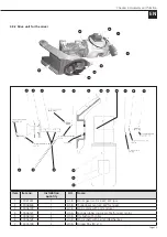
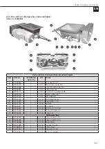
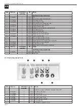
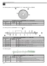
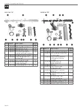
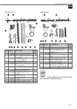
4.9.5 Drive shaft in the pump hopper

1

2


3

4

5

6

7

8

9

10 11 12 13 14

Drive shaft in pump hopper

Item  Item no.

Installation

quantity

UQ

Name 

1

10041877

1

Units

Drive shaft with Rotex coupling

2

10041878

1

Units

Sprocket for Rotex coupling

10019580

1

Units

Deep groove ball bearing 6309

4

10019581

1

Units

6309 Z deep groove ball bearing(s)

5

10004599

Units

Retaining ring, d = 45 mm

6

10004598

1

Units

Retaining ring, d = 100 mm

7

10006045

1

Units

Spacer sleeve

8

10005457

4

Units

Allen screw M8 x 25

9

10004978

4

Units

Oval head screws M5 x 10

10

10005351

1

Units

Screw M10 x 70

11

10004900

1

Units

10.5 mm washer

12

10004828

1

Units

M10 nut

13

10005312

1

Units

Splash guard washer, 10.5mm

14

10004887

1

Units

Lock washer M10

Summary of Contents for inoCOMB Cabrio

Page 1: ...EN Original Operating Manual Small Silo inoCOMB Cabrio Read this entire original operating manual before starting work ...

Page 2: ...ed to you or in urgent cases contact us directly We work constantly to further develop our products and reserve the right to make changes for technical reasons relating to building legislation Yours faithfully INOTEC GmbH Legal notice Address INOTEC GmbH Daimlerstraße 9 11 79761 Waldshut Tiengen Germany Tel 49 0 7741 6805 666 Fax 49 0 7741 6805 665 Email info inotec gmbh com Web www inotec gmbh co...

Page 3: ...l container 11 3 6 Mixer motor 11 3 7 Pump motor 11 3 8 Metering shaft 11 3 9 Mixing shaft 11 3 10 Pump shaft 11 3 11 Rotor Stator 12 3 12 Noise emission 12 3 13 Operating conditions 12 4 Assembly and function 12 4 1 Scope of delivery inoCOMB Cabrio 12 4 2 Functionality 12 4 3 Sequence of assembly 13 4 4 Components 14 4 4 1 Description of the components 14 4 4 1 1 Frame with pull out frame for pum...

Page 4: ...13 Mixing shaft for inoPOWERMIX S L mixing tube 34 4 9 14 Metering shaft 34 4 9 15 Pump shaft for set D and Ü 35 4 9 16 Rotor Stator 35 4 9 17 Set D 36 4 9 18 Set Ü1 36 4 9 19 Set Ü2 37 4 9 20 Set RS 37 5 Transport and storage 38 5 1 Safety instructions for transport 38 5 2 Transport inspection 38 5 3 Damage report 38 5 4 Complaints 38 5 5 Packaging 38 5 6 Transporting the used machine in the vehi...

Page 5: ...12 2 Dismantling 55 12 3 Disposal 55 13 Systems 56 13 1 EC declaration of conformity 56 13 2 General Terms of Business of the company INOTEC GmbH 57 13 3 Feeding and earthing 58 13 3 1 Circuit diagram Load circuits 01 59 13 3 2 Circuit diagram Load circuits 02 60 13 3 3 Circuit diagram Direction of rotation changeover 61 13 3 4 Circuit diagram Contactor control 62 13 3 5 Circuit diagram Sensors 63...

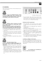
Page 6: ...nual 1 3 1 Purpose of this operating manual The operating manual is used to provide information to the operating manager assembly fitters and machine operators on the construction site It contains important instructions for safe use optimum results and a long service life DANGER Risk of incorrect operation Failure to observe the operating manual could put the operator s life and health at risk and...

Page 7: ...be fed with powdered material from sacks from one way containers with the inoFLEX Duo dry conveying unit from big bags with an attachment bonnet or with the big bag box Mono In the mixing phase a paste like product is created by adding water The material is pumped to the processing location by means of mortar hoses There it is applied to walls and ceilings with appropriate spray adhesive guns or a...

Page 8: ... and or bursting con veyor hoses Before disconnecting the conveyor hoses make sure that the hoses are depressurised To do so check the pressure indicator on the mortar pressure gauge The pressure in dicator must display 0 bar Before opening the hose coupling let the small silo ino COMB Cabrio run in reverse to release any pressure To do this press the Reverse pump pushbutton until the pres sure di...

Page 9: ...ctional ity of the machine Do not make any changes additions or conversions to the machine without first consulting INOTEC GmbH and obtaining its written approval Otherwise the op erating license will become void 2 2 4 Cleaning and maintaining the machine WARNING Cleaning and maintenance work can put the safety of operating staff at risk and impair the functionality of the machine 1 Switch off the...

Page 10: ...rating personnel as well as property damage to the inoCOMB Cabrio or other assets 2 5 Responsibility of the operator Only use trained or instructed personnel to operate the inoCOMB Cabrio small solos Define employees responsibilities for operating setting up maintaining and servicing the machine clearly Only task untrained staff or individuals who have not re ceived any instruction with operating ...

Page 11: ...ng on the consistency of the material observe the material manufacturer s instructions 3 3 Mortar pressure gauge Automatic shutdown 40 bar 3 4 Water measuring system Pressure being too low min 3 bar at 1 500 l h Pressure reducer ex works setting 2 5 bar Solenoid valve 24 V Supply line inch water pipe to be supplied by customer 3 5 Material container Filling quantity material con tainer approx 200 ...

Page 12: ...0 l 15 bar Item no 10043991 _____________________________ For scope of delivery see accessories 4 2 Functionality The small silo inoCOMB Cabrio is used for mixing and con veying pumpable mineral or organic products materials up to approx 8 mm grain size Dry mortar screed material or floor levelling compounds pre mixed by the material manu facturer can be used The material hopper of the small silo ...

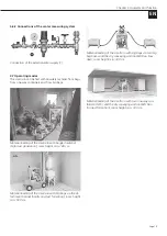
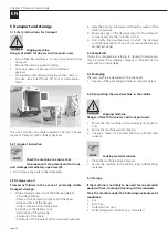
Page 13: ...e shaft in the lower area of the pump hopper and insert it into the Rotex coupling of the drive shaft 4 Insert the suction flange into the opening provided on the pump hopper 1 Place the pump unit rotor stator 2 on the suction flange and connect the pump unit to the pump shaft 3 Then fit the assembly 4 pres sure flange with mortar pressure manometer and the hose coupling to the pump unit Fix the t...

Page 14: ...to the socket provided on the side of the switching cabinet 10 Remove the green protective cap from the materi al hopper and secure the mixing tube to the material hopper with the two eccentric locks Make sure that the mixing shaft is properly connected to the metering shaft This sectional view shows the connection from the motor left to the metering shaft and from the metering shaft to the mixing...

Page 15: ... of the switching cabinet 4 4 1 4 Water measuring system The water measuring system is firmly connected to the frame of the machine The connection for the external wa ter supply line min 3 4 is located on the water measuring unit The water supply button is also attached to the frame The water flow button and the needle valve are used to make a rough adjustment of the water supply on the water flow...

Page 16: ... as the mixer is switched on the pushbutton lights up 4 5 1 3 Reverse pump If this pushbutton is pressed the pump runs in reverse e g if a stopper forms in the material hose 4 5 1 4 Probe On Off This switch turns the level probe in the pump hopper on and off 4 5 1 5 Pump speed The pump speed or the desired material flow rate is regulat ed with the potentiometer knob 4 5 1 6 Illuminated button Cove...

Page 17: ...mixing metering and pump shafts Danger of death due to being pulled into the machine and crushed When the motors are running the metering shaft ro tates in the material hopper the mixing shaft in the mixing tube and the pump shaft in the pump hopper Do not reach into the rotating mixing or pump shaft Do not bring any objects into the rotating mixing or pump shaft 1 Before working on the mixing or ...

Page 18: ...of property damage due to es caping water 1 Interrupt the external water supply by closing the water valve 2 In order to release the pressure approx 2 bar open the water drainage valve on the water measuring sys tem under the pressure reducer 3 Remove the hose from the external water supply 4 Do not point the water jet at other people or yourself NOTE Use an external site compressor for processing...

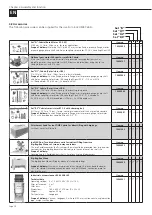
Page 19: ... silo with bagged material high dust generation room height min 180 cm Material loading of the small silo with big bags via the at tachment bonnet hardly any dust formation room height min 500 cm Material loading of the small silo with big bags via two big bag boxes and the dry conveying unit inoFLEX Duo low dust room height min 180 cm Material loading of the small silo with two one way con tainer...

Page 20: ...tem no 10043989 P Set RS Cabrio rotor stator R7 1 5 with clamping bar Ø 115 mm 50 l min 15 bar for e g coarse grained material such as grouted concrete Scope of delivery Suction flange pressure flange mortar pressure gauge rotor stator R7 1 5 with clamping bar coupling M part 50 2 IT Item no 10043991 P Attachment hood for inoCOMB Cabrio for direct filling with big bags without cover for filler hol...

Page 21: ...e adapter for each vibrating unit Item no 10038995 P P P P Vibrator with vibrating bars for OWC and big bags The vibration unit is stuck directly into an OWC or big bag and secured with a tension belt For non flowing powder material in an OWC or big bag Prevents tunnel formation or bridges Scope of delivery Vibrating unit assembled on plate with vibration rods including 230 V connecting cable and ...

Page 22: ...41544 10041545 10008346 010 10008346 011 P P P P P P P P P P P P P P P P P P P P P P P P Coupling reducer For connecting two mortar hoses or as a reduction in machine output 50 V piece 42 V piece 50 V piece 35 M piece 42 M piece 35 M piece Item no 10041187 10022100 10022097 P P P P P P P P P P P P Plaster piece with GEKA coupling For cleaning mortar hoses 50 M piece 35 M piece 42 V piece Item no 1...

Page 23: ...eel steel special assembly lubricant spray 400 ml tin connecting coupling for compressor Geka claw coupling bench hammer 300 g hose clamp 1 2 and 3 4 clamp ing range Stanley FatMax tool box Item no 10043923 P P P P Pump shaft for set Ü with Rotex coupling without sprocket Pump shaft for set D with Rotex coupling without sprocket Sprocket for Rotex coupling Item no 10041876 10042437 10041878 P P P ...

Page 24: ...lation quantity Number of parts in this position as they are installed in the original small silo inoCOMB Cabrio UQ Unit of quantity of this item Name Name of the spare part NOTE Use the order form at the end of this op erating manual to order spare parts 4 9 1 Overview of the individual assemblies of the small silo 1 5 2 4 6 3 Item Name 1 Frame rack with pull out frame for pump hopper material ho...

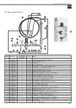
Page 25: ...uantity UQ Name 1 10041407 1 Units Worm gear motor 4 kW 373 rpm 2 10006536 1 Units Three phase motor 4 kW for mixer 3 10006139 1 Units Motor plate with bolt and seal 4 10006141 1 Units Sponge rubber square profile for mixer motor 5 10006140 2 Units Dry bush with collar 6 10006138 1 Units Motor shaft with bell and feather key 7 10004148 2 Units Oil seal 55 x 80 x 10 ...

Page 26: ...004962 1 Units M shape detent edged washer M12 16 10005452 1 Units Allen screw M 12 x 30 galvanised 17 10006354 1 Units Terminal board box for gear motor 18 10015178 1 Units Motor connection cable with CEE plug 19 10015262 1 Units CEE plug 5 x 16 4 9 3 Pump hopper 1 2 3 4 5 Item Item no Installation quantity UQ Name 1 10039224 1 Units Complete safety switch 1 1 10034395 1 Units Actuator for safety...

Page 27: ...31 1 Units Straight M 6 grease nipple 6 10004154 1 Units White rubber seal 7 10022478 1 Units TW male part 8 10022476 1 Units TW protective cap 9 10016824 1 0 2 m Steel cable 2 mm 9 1 10018183 2 Units Ferrules 10 10006057 2 Units Stud bolts 10 1 10005332 2 Units Split pin 4 x 32 mm 11 10016544 2 Units M16 x 300 eyebolts 12 10005228 2 Units Collar nut Chain gear box 13 10006043 1 Units Chain wheel ...

Page 28: ...3 10019580 1 Units Deep groove ball bearing 6309 4 10019581 1 Units 6309 Z deep groove ball bearing s 5 10004599 1 Units Retaining ring d 45 mm 6 10004598 1 Units Retaining ring d 100 mm 7 10006045 1 Units Spacer sleeve 8 10005457 4 Units Allen screw M8 x 25 9 10004978 4 Units Oval head screws M5 x 10 10 10005351 1 Units Screw M10 x 70 11 10004900 1 Units 10 5 mm washer 12 10004828 1 Units M10 nut...

Page 29: ...1 4 IT 9 10006466 1 Units Pressure gauge 0 10 bar 1 4 below 10 10039020 1 Units Pressure reducer D06FN low pressure 10 1 10006464 1 Units Brass sieve cup with 1 4 hole 10 2 10006518 1 Units Replacement strainer for pressure reducer 11 10017912 2 Units Mini ball valve 1 4 IT ET 11 1 10004302 1 Units PE seal hard 18 8 x 13 5 x 2 12 10006463 1 Units Magnetic valve 2 2 way 1 2 24 V complete 13 1000647...

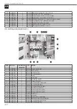
Page 30: ...tem no Installation quantity UQ Name 1 10041987 1 Units Power supply unit 2 10041060 1 Units CPU control 3 10041061 2 Units Extension CPU 4 10041107 1 Units Coupling relay s 5 10041062 1 Units Relay 6 10041101 1 Units Level relay 7 10041117 1 Units Frequency inverter 8 10041074 2 Units Power contactor 9 10043194 1 Units Circuit breaker C25 3 fold 10 10043191 4 Units Circuit breaker B16 11 10041951...

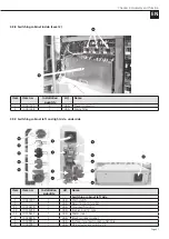
Page 31: ...ht side underside 1 2 3 4 5 1 2 3 6 4 5 7 8 9 1 Item Item no Installation quantity UQ Name Switching cabinet left side 1 10041077 1 Units Main switch 2 1 Units Remote control socket 2 1 10015618 1 Units Mounted housing 2 2 10015398 1 Units Socket insert 4 pole 2 3 10015613 1 Units Metal cover 3 10039975 1 Units Black mounted socket 4 10039976 1 Units Surface mounted socket outlet blue 5 10043951 1...

Page 32: ... 1 Units Socket insert 6 pole 6 1 Units CEE mounting socket straight 7 1 Units CEE mounting socket straight 8 1 Units Attachment box for mortar pressure gauge 8 1 10015618 1 Units Attachment housing straight 8 2 10015398 1 Units Socket insert 4 pole 9 10015613 2 Units Metal covers unoccupied connections Item Item no Installation quantity UQ Name Switching cabinet underside 1 10044251 1 Units Air i...

Page 33: ...s Lamp holder LED red 6 10044360 1 Units Indicator lamp blue complete 6 1 10044361 1 Units Lamp holder LED blue 4 9 11 Mixing tube inoPOWERMIX S Plus with mixing shaft and mixing tube cover 7 2 6 3 1 4 5 Item Item no Installation quantity UQ Name 10044030 1 Units Mixing tube inoPOWERMIX S Plus with mixing shaft and mixing tube cover 1 10044167 1 Units inoPOWERMIX PU inlay short with wide outlet 2 ...

Page 34: ... shaft for inoPOWERMIX S for adhesive and reinforcement mortar 1b 10041033 1 Units Mixing shaft for inoPOWERMIX S with PU scraper for masonry mortar 1b 10044009 1 Units Mixing shaft for inoPOWERMIX L with PU scraper for masonry mortar 2 10040694 1 Units Allen screw 8 x 12 mm left hand thread 3 10040419 1 Units Splash guard washer 4 10044011 1 Units PU scraper for mixing shaft inoPOWERMIX S L 4 9 1...

Page 35: ...out sprocket 3 10041878 1 Units Sprocket for Rotex coupling 4 9 16 Rotor Stator 1 3 5 7 2 4 6 8 Rotor stator depending on set and application Item Item no Installation quantity UQ Name 1 2 10022556 10022515 1 1 Units Units Set D Rotor D7 2 5 S Set D Stator D7 2 5 S 3 4 10041243 10041242 1 1 Units Units Set Ü1 Rotor 1R6 Set Ü1 Stator 1R6 maintenance free 5 6 10044018 10044019 1 1 Units Units Set Ü2...

Page 36: ...Coupling M part 35 1 1 2 IT 1 pcs 4 9 18 Set Ü1 3 10 1 2 12 5 4 7 6 8 9 11 Item Item s Item name Quan tity 1 10006062 Suction flange for Ü50 stator 1 pcs 2 10041272 Pressure flange straight V2A for Ü 50 jacket 1 pcs 3 10041876 Pump shaft inoCOMB for Ü 50 jacket with Rotex coupling 1 pcs 4 10016799 Double nut M 16 spacer sleeve SHK 2 pcs 5 10004830 M16 nut 4 pcs 6 10041243 Rotor 1R6 tool steel hard...

Page 37: ...m 9 10016799 Double nut M 16 spacer sleeve SHK 2 pcs 10 10004830 M16 nut 4 pcs 11 10041878 Sprocket for Rotex coupling 1 pcs 12 10042444 Metering shaft pitch 45 mm 1 pcs 4 9 20 Set RS 1 2 3 4 5 6 7 8 9 Item Item s Item name Quan tity 1 10042444 Metering shaft pitch 45mm 1 pcs 2 10041057 Suction flange R pump R jacket 1 pcs 3 10022887 Rotor R7 1 5 1 pcs 4 10023395 Stator R7 1 5 with clamping strip ...

Page 38: ...ure of the recipient at the customer s premises 2 Have the transport damage confirmed by means of the driver s signature 3 Send one copy of the damage report to the transport company and another to Inotec GmbH 4 And clarify the possible ways in which the damage could be remedied with one of our service centres see second last page 5 4 Complaints Claims for compensation relating to transport damage...

Page 39: ...play 0 bar Before opening the hose coupling let the small silo ino COMB Cabrio run in reverse to release any pressure To do this press the Reverse pump pushbutton until the pressure display on the mortar pressure gauge shows 0 bar Pushbutton Reverse pump Use only conveyor hoses which are permissible with an operating pressure of 40 bar and a burst pressure of 120 bar and are in a technically perfe...

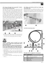
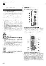
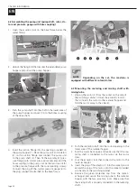
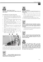
Page 40: ...o the plug connection attached to the base frame 3 2 4 5 6 1 NOTE Depending on the set the machine is equipped with different rotors stators 6 3 Mounting the metering and mixing shaft with mixing tube 1 Unplug the motor 2 from the socket on the side of the switching cabinet Unlock the eccentric lock 3 that connects the motor to the material hopper and fold the motor away to the side 4 1 2 3 4 2 Pu...

Page 41: ...water Follow the instructions of the manufacturer of the drying material NOTE To ensure sufficient water pressure in dependent of the pressure of the supply line we rec ommend the use of a booster pump WARNING Water jet Risk of injury and risk of property damage due to es caping water 1 Interrupt the external water supply by closing the water valve 2 In order to release the pressure approx 2 bar o...

Page 42: ... 2 3 litres of milk of lime mortar slurry or wallpaper paste into the delivery hose as pre lubrica tion and then connect it to the mortar coupling 3 Start the mixer motor by pressing the Mixer ON but ton and fill the pump hopper up to the upper probe rod 4 Then start the pumping process by pressing the Pump button The button of the pump lights up green and the button of the mixer flashes ready mes...

Page 43: ... long term lung damage or other adverse health ef fects The machine operator or people working in the dust area must each wear a dust mask when cleaning the machine Find out about the technical rules for hazardous sub stances TRGS 559 Mineral dust on the homepage of the German Social Accident Insurance Institution www bgbau de Warning Risk of injury posed by powdery and paste like material When fi...

Page 44: ...sting it on the needle valve of the water fitting Material too runny Reduce the water supply by re adjusting it on the nee dle valve of the water fitting NOTE Ensure that the change in consistency may take some time to become noticeable depend ing on the length of the hose approx 20 seconds per 15 m hose length Therefore adjust the water supply at the needle valve only by turning it a small amount...

Page 45: ...e machine and crushed When the motors are running the metering shaft ro tates in the material hopper the mixing shaft in the mixing tube and the pump shaft in the pump hopper Do not reach into the rotating mixing or pump shaft Do not bring any objects into the rotating mixing or pump shaft 1 Before working on the mixing or pump shaft disconnect the external power supply main switch off Only loosen...

Page 46: ...out at the end of the mortar hose 6 Stop the machine by pressing the double pushbutton Pump Reset 0 7 Now uncouple the quick coupling on the hose connec tion on the mortar pressure gauge by opening the two cam levers Put a sponge ball into the hose and then reconnect the mortar hose 8 Fill some more water into the pump hopper and start the machine by pressing the double pushbutton Pump Reset I In ...

Page 47: ...he mixing tube frame with the two eccentric locks At the end of work place the cleaned mixing tube back into the pump pull out frame Close the mixing tube receptacle with the green cover 1 2 3 22 For possible cleaning of the material hopper residue emptying pull the plug of the motor 1 out of the socket on the side of the switching cabinet 23 Unlock the eccentric lock 2 that connects the motor to ...

Page 48: ...mp hopper Do not reach into the rotating mixing or pump shaft Do not bring any objects into the rotating mixing or pump shaft 1 Before working on the mixing or pump shaft disconnect the external power supply main switch off Only loosen the screw of the protective grids when the machine is switched off 2 Pull out the mains plug 3 Secure the machine against unexpectedly being switched back on DANGER...

Page 49: ...et cover all the open ings that water must not penetrate into for safety and functional reasons 5 After cleaning remove all the covers which were at tached to protect against the water 11 1 Maintenance plan Have the machine inspected at a specialist workshop or at an INOTEC service centre Once a year Recommended Electrical inspection DGUV V3 by a qualified electri cian or at an INOTEC service cent...

Page 50: ...cking and remedying the fault or contact the Inotec Service team see the address list for INOTEC service centres at the end of the document or call the INOTEC service hotline on 49 7741 6805 777 WARNING Malfunctions can jeopardise the safety of the the safety of operating staff at risk and impair the functionality of the machine Proceed as follows where a fault occurs 1 Cut off the power supply in...

Page 51: ...e has tripped Check the RC fault indicator on the switching cabinet In the event of a fault in the frequency inverter or if the RCD or the fuse is tripped the cover grille warning light lights up red After eliminating the fault acknowledge the warning light with the red button at the Pump On switch Reset Machine operator Have the engines checked Have the fault remedied if necessary Service technic...

Page 52: ...tor checked and replaced with a new mo tor if necessary Have the electrical control checked and repaired if necessary Service technician qualified electrician Excessively high deliv ery pressure Reduce the length of the hose Machine operator Foreign matter in the metering or mixing shaft Switch off the machine and pull out the mains plug Check whether there is a foreign body or hardened material i...

Page 53: ...ust be dismantled Clamp the stator in a vice turn the rotor anticlockwise out of the jacket and remove the plugger Machine operator Worn or poorly lubri cated hoses Run the machine in reverse to reduce the mortar pressure Check the mortar pressure on the mortar pressure gauge If the pressure gauge shows 0 bar switch off the machine and pull out the mains plug Remove the mortar hose remedy the mate...

Page 54: ...by adjusting it on the needle valve of the water fitting Machine operator Con sistency fluctua tions The material supply or water quantity is fluctuating Switch off the machine and pull out the mains plug Check the mixing shaft and the pump shaft for adhering ma terial and clean and dry them before reinserting Check the water inlet screen clean the water screen if nec essary Check the water pressu...

Page 55: ...ine at 49 7741 6805 777 DANGER Electrical voltage Danger of death due to electric shock When switched on electrical components can cause uncontrolled movements and lead to serious injury 1 Switch the machine off To do this turn the red rotary switch to the horizontal position 0 2 Pull out the mains plug and finally disconnect the ma chine from the electrical supply 12 2 Dismantling Clean and disma...

Page 56: ...s of the EC Directive 2006 42 EC This declaration will become void in the event of any modification made to the machine without our approval Designation of the unit inoCOMB Cabrio Machine model Small silo Item number 10042612 Applied harmonised standards DIN EN 12100 Safety of machinery DIN EN 60 204 1 Electrical equipment of machines Part 1 general requirements DIN EN 13857 Safety of Machinery Sa...

Page 57: ...ht to deduct the working hours spent at current billing rates and or a percentage of the value of the goods from the credit note and with respect to machine returns we reserve the right to carry out a leasing calculation using current leasing rates 6 Retention of title extended retention of title I INOTEC GmbH retains title to the delivered goods until all receivables from the concluded contract i...

Page 58: ...age 58 EN Chapter 13 Systems 13 3 Feeding and earthing Inotec GmbH Daimler Str 9 11 D 79761 Waldshut Tiengen L3 2 L2 2 L1 2 Q4 Q3 L L G1 R3 L2 P2 N L2 L1 P1 L3 L2 L1 F4 F3 F2 PE N 1 L3 L2 Q1 F1 Q2 L1 XS1 ...

Page 59: ...Page 59 EN Chapter 13 Systems 13 3 1 Circuit diagram Load circuits 01 Inotec GmbH Daimler Str 9 11 D 79761 Waldshut Tiengen Q5 M1 E1 F7 F6 L1 2 PE N 1 L3 2 L2 2 L1 2 L2 2 L3 2 N 1 PE MV F5 ...

Page 60: ...Page 60 EN Chapter 13 Systems 13 3 2 Circuit diagram Load circuits 02 Inotec GmbH Daimler Str 9 11 D 79761 Waldshut Tiengen Q7 F10 M6 K3 Q6 PE N 1 L3 2 L2 2 L1 2 L2 2 L3 2 N 1 PE L1 2 F9 M5 ...

Page 61: ...ion changeover Inotec GmbH Daimler Str 9 11 D 79761 Waldshut Tiengen H1 Q3 A3 13 5 Steuerung ein Q3 A2 12 5 Bestriebsbereit Pumpe Ein 11 5 A1 I1 Pumpe Aus 12 5 A2 I5 Netzuberwachung 11 5 A1 I7 S2 Q4 Q3 Q4 P2 K2 L L K2 Q3 S1 L L P1 Steuerung ein Netzüberwachung Phasenfolge ...

Page 62: ...2 12 5 Umrichter Storung K3 Q6 A1 Q0 Q1 Q2 Q0 Q1 Q2 Q7 Ruttler ein 12 5 A2 Q0 Wasserdruck 12 5 A2 Q1 H2 Wasserdruck 12 5 A2 Q1 H3 Morteldruck 13 5 A3 Q1 H5 Storung Pumpe oder Abdeckgitter offen 13 5 A3 Q2 H6 Wasserventil Wasserpumpe ein Mischer ein Rüttler ein Wasserdruck Fernbedienung Mörteldruck Störung Pumpe oder Abdeckgitter offen T1 MA ...

Page 63: ...tr 9 11 D 79761 Waldshut Tiengen Fernbedienung 11 5 A1 I2 L L L L S4 B1 Morteldruck 11 5 A1 I3 K1 Mortelniveau 11 5 A1 I4 Wasservorlauf 12 5 A1 I5 Druckwachter Wasser 12 5 A1 I6 S5 B2 X2 A1 PE PE A2 COM X1 X2 MIN MAX DOLD MK9151 12 K1 min max COM Mörteldruck Blindstecker Niveaurelais ...

Page 64: ...er 13 Systems 13 3 6 Circuit diagram Operating switch Inotec GmbH Daimler Str 9 11 D 79761 Waldshut Tiengen I2 A2 12 5 Sonde I1 A2 12 5 Mischen L L I0 A2 12 5 Mischen S6 S6 S8 Aus Ein Aus H8 Q0 A3 13 5 Mischen Ein L L ...

Page 65: ...5 EN Chapter 13 Systems 13 3 7 Circuit diagram Pump Inotec GmbH Daimler Str 9 11 D 79761 Waldshut Tiengen V1 L1 PE N 1 L3 L2 F31 3 T1 M7 A1 S7 R2 S211 YASKAWA PE L L T1 MA Pumpe Rückwärts Abdeckgitter L L L L ...

Page 66: ...resse Querverweis NLC 055 024D 08I 04QRD 05A Starttaste S2 14 6 4C 14 2C Fernbedienung S4 14 8 1C Mörteldruck B1 12 8 2C Mörtelniveau K1 12 8 3C Wasservorlauf X2 S5 14 8 4C Druckwächter Wasser X2 S5 24 8 5C Netzüberwachung P2 12 6 2C Versorgung Nano 14 1C 14 2C 14 2C Wasserventil Wasserventil Wasserpumpe ein Wasserpumpe ein Mischer ein Mischer ein Pumpe Vorwärts Pumpe Vorwärts 4Y1 x1 Q5 A1 Q6 A1 T...

Page 67: ...tal I O PHOENIX CONTACT 2 1 A2 NLC IO 06I 04QTP 01A H1 x1 H2 x1 Betriebsbereit Fernbedienung aktiv Wasserdruck Rüttler ein 14 4C Querverweis Symbolische Adresse Funktionstext Adresse 2 1 6 3C S1 22 Stoptaste 7 8C T1 MA Umrichter Storung 9 2E S6 2 Mischen 9 2E S6 4 Automatik 9 3E S6 6 Pumpen 14 4C 14 4C 14 4C Q7 A1 H3 x1 ...

Page 68: ...tr 9 11 D 79761 Waldshut Tiengen A3 1 2 PHOENIX CONTACT Digital I O NLC IO 06I 04QTP 01A H6 x1 14 6C 14 6C 14 6C 1 2 Adresse Funktionstext Symbolische Adresse Querverweis 14 3C Mörteldruck Storung Pumpe oder Abdeckgitter Steuerung ein H5 x1 K2 A1 7 7D 7 8D 6 4D Mischer Ein H8 x1 9 5D ...

Page 69: ...Page 69 EN Chapter 13 Systems 13 3 11 Circuit diagram Nano 04 Inotec GmbH Daimler Str 9 11 D 79761 Waldshut Tiengen PE L L PE L L 2 1 A1 NLC 055 024D 08I 04QRD 05A 11 5 C 11 5 B A2 12 5 C A3 13 5 D ...

Page 70: ...customer Consultant Date Number Item no Item name Our General Terms of Business Delivery and Payment apply The customer has been made aware of these terms and agrees to the application of the same All goods shall be owned by us until we receive complete payment pursuant to Section 449 of the German Civil Code ...

Page 71: ... Terms of Business 57 I Installation 39 Intended use 7 L Locations 72 M Maintenance plan 49 Mixing unit metering shaft and mixing tube with mixing shaft 17 N Notices on the machine 9 O Operating modes 19 Operation use 44 Order form 70 P Packaging 38 Personal protective equipment PPE 10 Personnel qualification 10 Pump unit pump motor pump shaft rotor stator and mortar pressure gauge 17 R Responsibi...

Page 72: ... sales partner English language 72 INOTEC GmbH Headquarter Daimlerstraße 9 11 79761 Waldshut Tiengen Germany Phone 49 7741 6805 675 Fax 49 7741 6805 665 E Mail j tetling inotec gmbh com Wherever you are we re there too ...

Page 73: ...uct range Delivery pumps Mixing pumps Mixers Delivery systems OWC technology Silo technology Airless devices Cutters Grinders One handed guns Accessories spare parts Waste water systems Tillage Power tools electrical appliances Compressed air compressors Heaters air dehumidifiers high pressure cleaners ...

Reviews: