15
C.
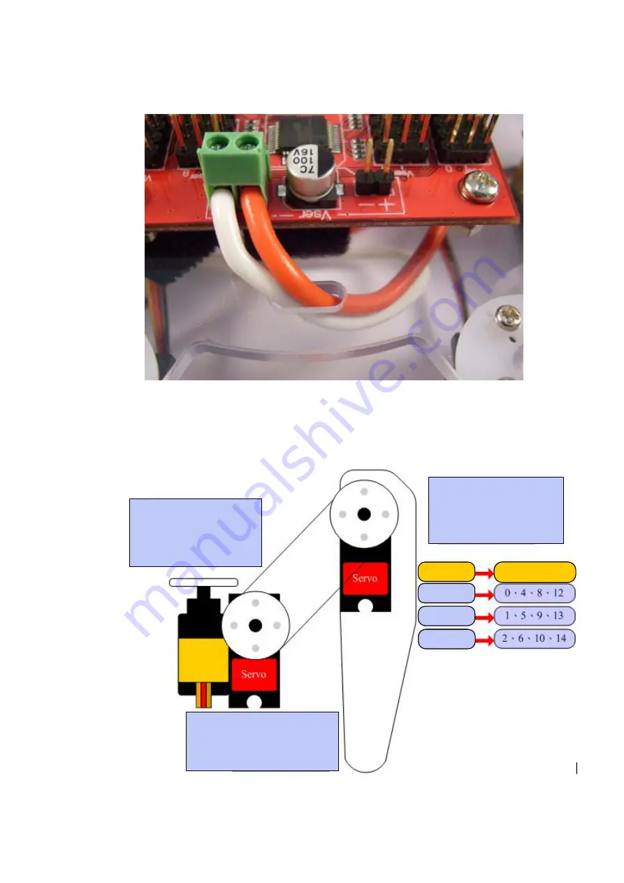
Pass the red and white wires upward through the hole and then fix them into
the power input terminals with the screws.
While installing, please pay attention to the polarity. The red wire should be
connected to the “+” terminal and the white wire should be connected to the
“-” terminal.
Step 10: Install Servo Wires to Servo Commander 32
Connect the control lines of each servo to the corresponding pins on Servo
Commander 32. Please note whether the module IDs and servo IDs defined in the
program agree with the module IDs and servo IDs on the Servo Commander 32 to be
connected. The pin assignments for wire connection are as follows.
[Configuration of the IDs of the joints]
Inner joint: This servo is
connected to the pins with
smaller ID number, e.g.,
the position 0 in case of
0-2.
Outer joint: This servo is
connected to the pins with
larger ID number, e.g., the
position 2 in case of 0-2.
Joint part
Servo ID
Inner joint
Middle joint
Outer joint
Middle joint: This servo is
connected to the pins with
intermediate ID number, e.g.,
the position 1 in case of 0-2.


