


8120-B1 User’s Guide
Commonly used buttons
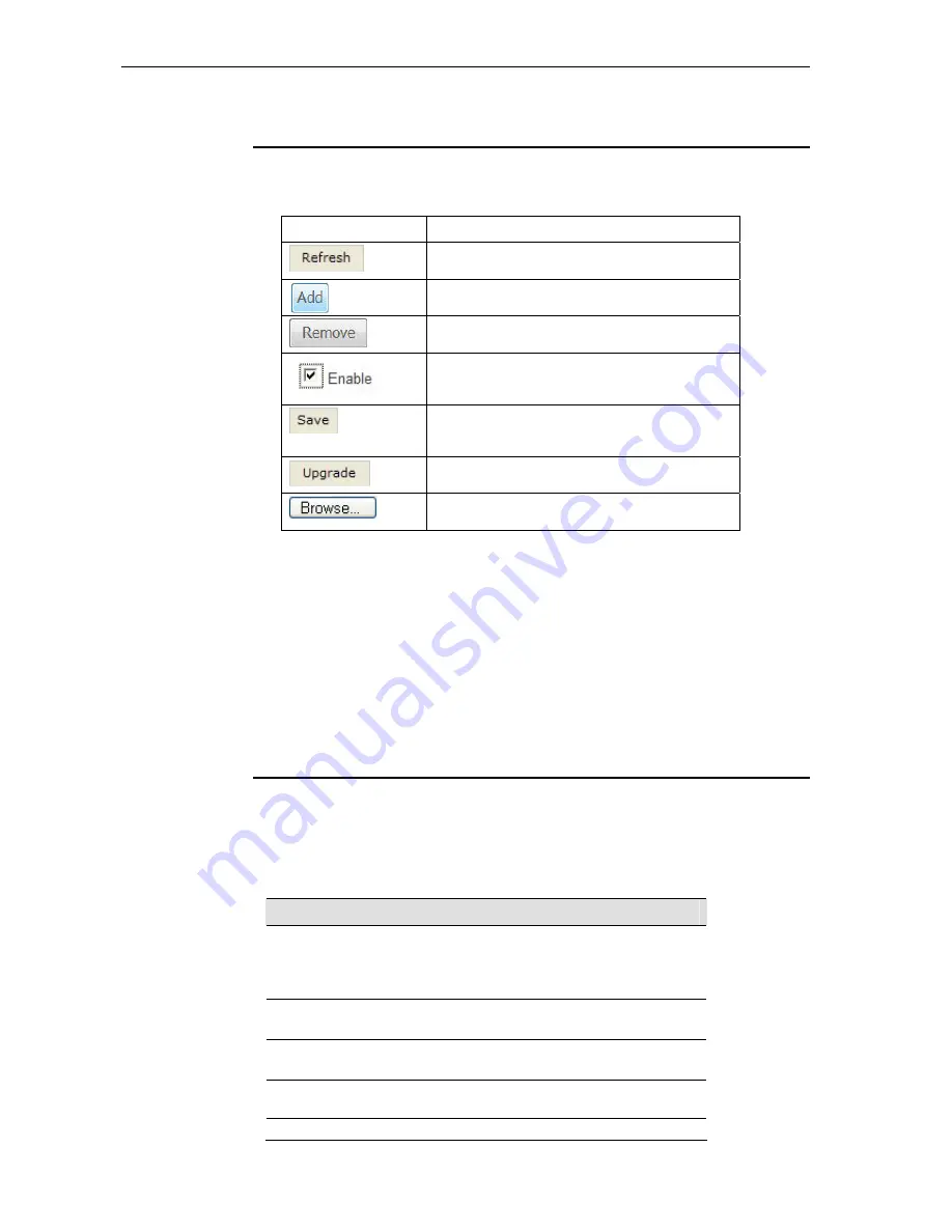
The following buttons are used throughout the web pages:
Button Function
Click this button to refresh the information on this
page to get the real time updated information.
Click this button to create an entry into the list.
Click this button to delete (remove) an entry from the
list.
Check button – these appear on many configuration
pages. You will be asked to check if you want this
feature be selected.
This button appears on every configuration page.
Click on this button once you are through with the
changes and decide to save the made changes.
Allows you to upgrade to the new configuration file
attached using the Browse button.
Browse to your file location for Upgrading software or
new configuration.
The following terms are used throughout this guide in association with these buttons:
Click
– point the mouse arrow over the button, menu entry or link on the screen and
click the left mouse button. This performs an action, such as displaying a new page or
performing the action specific to the button on which left mouse button is clicked.
Select
– usually is used when describing which radio button to select from a list, or
which entry to select from a drop-down list. Point the mouse arrow over the entry and
left-click to select it. This does not perform an action – you will also be required to click
on a button, menu entry or link in order to proceed.
Testing your Setup
Once you have connected your hardware and configured your PCs, any computer on
your LAN should be able to use the device to access the Internet.
To test the connection, turn on the device, wait a few seconds until the device finishes
booting up, then verify that the LEDs are illuminated as follows:
LED
Behavior
Solid green to indicate that the device is turned on. If
this light is not on, check the power cable
attachment. Also, check the on/off button in the rear
panel to see if it’s in the “on” position.
PWR
Solid green to indicate that the device can
communicate with your LAN.
LAN
Solid green to indicate that the device has
successfully established a connection with your ISP.
DSL
Should be blinking or solid green if d
ata being
transmitted
PPP
ALM
Lit or blinking after device booting up indicates data error
10


