background image

16

Installation Guidelines

This guide outlines the process for installing 
the IsatDock2 MARINE in conjunction with an 
Inmarsat IsatPhone 2 handset and antenna.
This kit must not be used with any other device 
other than the Inmarsat IsatPhone 2 handset 
and other compatible accessories.

•  Only trained personnel should install 

communication equipment.

•  Ensure that the unit is protected from dirt 

and moisture.

•  Select an area to mount components where 

there is no interference with other objects.

•  A strong mounting surface should be 

chosen to ensure the terminal doesn’t 
loosen over time.

•  Mount all components securely for safe day 

to day operation. Always use the supplied 
mounting hardware.

•  Leave space around the unit to allow airflow 

and ensure there is adequate clearance for 
cables.

•  Ensure the units can be easily accessible for 

servicing.

electrical noise that interferes with the 
electrical radio system operation. The 
ignition system is the most common 
source of electrical noise interference. 
Before you begin installation, ensure 
that the ignition wiring and connections 
to the battery are in good working 
condition.

• 

Install provided fuses into the +BATT and 
ignition sense (accessory) wires.

WARNING

Do not connect the IsatDock power cable to power 
the unit until the full installation is completed.

Routing Cables 

•  Route cables so they are protected from 

pinching, sharp edges, and crushing.

•  Use grommets wherever a cable must pass 

through a hole in a metal panel

•  Keep all in-line connectors accessible.
•  For an extra clean installation, a hole may 

be driven through the surface directly 
behind the docking station.  

Guidelines for Electrical Connections

The system is designed to operate 10 to 32 Volt 
DC electrical systems only
• 

The best power connection point for 
the positive primary power lead is the 
positive terminal of the battery. Often, 
direct connection to the battery is 
inconvenient, and you may find it easier 
to connect the positive leads to the 
starter solenoid. Always select a point as 
close as possible to the battery.

• 

Connect the negative primary power 
leads to a good ground point on the 
vessel or at the battery. If you must 
attach the negative primary power 
lead directly to the negative pole of the 
battery.

• 

Many parts of a vessel can produce 

Summary of Contents for IsatDock2 MARINE

Page 1: ...IsatDock2 MARINE User Manual Inmarsat Approved ...

Page 2: ...2 ...

Page 3: ...d by BEAM Communications Pty Ltd BEAM is believed to be accurate and reliable However no responsibility is assumed by BEAM for its use or for any infringement of patents or other rights of third parties which may result from its use No license is granted by implication or otherwise under any patent or patent rights of BEAM BEAM reserves the right to change specifications at any time without notice...

Page 4: ...AM specializes in Voice Data Tracking and customized solutions BEAM develops innovative products and services to meet market demands and niche applications BEAM sleadingedgeproductsaredeployedinawiderangeofverticalmarkets includingMaritime Transport Government Defence Mining Construction Forestry EmergencyServices ReliefAid TelemetryandRuralTelephony Supported by a dedicated team of professionals ...

Page 5: ...iguration Tool MS Windows Install SMS Short Message Service Mobile Originating Describes a call initiated by the IsatDock Mobile Terminating Describes an incoming call being answered by the IsatDock IsatPhone 2 The Inmarsat IsatPhone 2 handset The symbol mark and logos are owned by the respective companies of which the symbol follows Any use of such marks by BEAM Communications is under license Ot...

Page 6: ...kit Active ISD944 70m cable kit Active ISD945 80m cable kit Active ISD946 90m cable kit Active ISD947 100m cable kit Active Additional Accessories ISD960 IsatDock2 Adapter RST055A UPS Battery Pack RST410 Man Down Pendant Kit See your service provider for pricing and availability of these quality BEAM accessories Additional Information For the latest in supporting software and documentation for Isa...

Page 7: ... Falcon Configuration using Remote Commands Equipment Overview 14 Docking Undocking IsatPhone 2 handset 15 Installation Guidelines 16 Routing Cables Guidelines for Electrical Connections Installation Procedure 17 Installing the IsatDock2 MARINE Cradle IsatDock2 MARINE Usage 25 Operation of the IsatPhone 2 Placing Voice Calls Mute Mode USB Driver Installation Personal Alert and Assistance Alert Ope...

Page 8: ...nside If a DC power supply is to be used its output must comply with the Safety Extra Low Voltage SELV requirements of IEC60950 Allconnectorsmustonlybeconnectedtoequipment portswhichcomplywiththeSafetyExtraLow Voltage SELV requirementsofIEC60950 POTENTIALLY EXPLOSIVE ATMOSPHERES Turn your phone OFF and DO NOT remove your battery or remove the IsatPhone 2 handset from the cradle when you are in any...

Page 9: ...when a person is within 55cm of the external antenna A person or object within 55cm of the external antenna could impair call quality and may cause the phone to operate at a higher power level than necessary and expose that person to RF energy in excess of that established by the FCC RF Exposure Guidelines As a precaution please maintain the maximum body distance possible from the antenna during c...

Page 10: ...ser is encouraged to try to correct the interference by one or more of the following measures Reorient or relocate the receiving antenna Increase the separation between the equipment and receiver Connect the equipment into an outlet on a circuit different from that to which the receiver is connected Consult the dealer or an experienced radio TV technician for help This device has been designed to ...

Page 11: ...ch as hospitals and on board aircraft Electronic Devices Most modern electronic equipment is shielded from RF signals However certain equipment may not be shielded against the RF signals from your wireless phone Pacemakers The Health Industry Manufacturers Association recommends that a minimum separation of six inches 6 be maintained between a wireless phone s antenna and a pacemaker to avoid pote...

Page 12: ...support and provide easy access to many features of IsatPhone 2 whilst docked such as Assistance Alert instant Personal Alert and Tracking DESIGN All in one design IP54 Maritime grade design High quality ABS plastic Enhanced phone docking mechanism Robust USB Audio Connection Accessible control buttons Dedicated Personal Alert button on dock Auto sensing off hook privacy handset Complete cover ove...

Page 13: ...ong beep followed by three short beeps Configuration Using Remote Commands Configuration instructions or Remote Commands can be sent to the terminal via SMS and most settings are supported that are normally accessible from Falcon Please refer to the Falcon user manual for more information NOTE Due to memory limitations it is recommended that users have no more than 20 SMS messages in their inbox I...

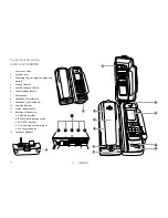
Page 14: ...r handset 6 Speakerphone Button 7 Microphone 8 IsatPhone 2 Eject Button 9 IsatPhone 2 not included 10 Function Buttons 11 Status Indication LED 12 Back Panel Connectors a USB Data Interface b BEAM Alert Loop connection c RJ11 POTS interface d DC power and accessory input e RJ9 Privacy handset 13 IsatDock2 Adapter 2 1 3 4 5 6 7 8 9 10 11 12 a b e c d 13 ...

Page 15: ...nsert by hand in the base of the IsatPhone 2 4 To dock the handset open the antenna slightly align the IsatPhone 2 with the phone tray and slide the handset down until it seats flush to the bottom of the tray Swing the phone down into the cradle by applying pressure to the top of the handset An audible click is heard when the phone is in the docked position 5 To remove the handset from the cradle ...

Page 16: ...sure that the ignition wiring and connections to the battery are in good working condition Install provided fuses into the BATT and ignition sense accessory wires WARNING Do not connect the IsatDock power cable to power the unit until the full installation is completed Routing Cables Route cables so they are protected from pinching sharp edges and crushing Use grommets wherever a cable must pass t...

Page 17: ...nd GPS antenna cables These cables are purpose built cables as approved by BEAM to manage the power requirements for the antenna system 1 Refer to the antennas installation guide for antenna mounting and location requirements 2 Connecttheantennacablelabelled GPS to theSMAantennaconnectorlabelled GPS 3 Connecttheantennacablelabelled Inmarsat totheSMAantennaconnectorlabelled SAT 4 ConnecttheGPS SMA ...

Page 18: ...of the antenna system is a vital part of the IsatDock2 MARINE system to ensure reliable functionality and drop free calls WARNING Changes or modifications not expressly approved by BEAM Communications could void the product warranty WARNING To satisfy FCC RF exposure requirements for mobile transmitting devices a separation distance of 55cm or more should be maintained between the antenna of this ...

Page 19: ...sses through the docking station and needs to be in place to create a seal against the o rings at the rear of the Dock and maintain the waterproof rating 2b Desk Mounting Orientation The IsatDock2 MARINE supports a desk mount configuration Depending on the users requirements the docking station supports both a flat and raised orientation on the desk To configure the IsatDock for a desk installatio...

Page 20: ...acy handset and the springless cup has enough height to allow the handset to rise up off the clip and out of the mounting cup 1 2 3 4 3 Privacy Handset Mounting Cup The Privacy Handset is conveniently mounted on to the IsatDock2 MARINE enclosure providing a local handset function The Privacy Handset connects to the docking station via a RJ9 connector The privacy handset is connected beneath the re...

Page 21: ...lears the lower mounting pip and can be removed from the docking station 4 Access to Rear Connector Bay For the IsatDock2 MARINE the external cable interfaces are at the rear of the docking station The cover panel creates the IP rating for the electrical interface and retains the cables in their respective channels The cover panel is fixed in place by seven screws a USB Data Interface b BEAM Alert...

Page 22: ... any one of these buttons will OPEN activate the loop when pressed To properly activate the Assistance Alert the loop needs to be OPEN for at least 2 seconds ie holding down the button for 2 seconds activates the Assistance mode NOTE If the BEAM Alert Loop is going to be used with an external button remember to enable this external loop in the Falcon settings Once enabled the loop will be armed an...

Page 23: ...sitive terminal of the battery It is recommended to add the 5A fuse supplied between them 4 Connect the YELLOW wire to the vessel accessory power If the accessory power is unavailable this may be connected to a switch It is recommended to add a 1A fuse between them The accessory wire enables the IsatDock2 MARINE to turn on and off as the vessel key is enabled or disabled If this function is not re...

Page 24: ...tted to the antenna connectors to allow routing of cables through a wall A clean installation free of any visible cabling can be achieved by running the interface cables from the connector bay along path A and through the same holes SMA Adapter GPS TNC Adapter GSPS RearCoverScrewedinPlace Therearcover oftheMARINEdockmustbescreweddown withatleastthefourscrewsindicatedbelow toensurethewaterproofseal...

Page 25: ... to charge the battery whilst docked If the battery temperature exceeds this IsatDock2 MARINE Usage Operation of the IsatPhone 2 Prepare the Inmarsat IsatPhone 2 Ensure that the IsatPhone 2 Handset has the latest compatible firmware installed For more information visit www beamcommunications com support isd2marine Starting Up 1 Retract the antenna on the IsatPhone 2 handset and place in slightly o...

Page 26: ...erminate the call Mobile Terminating 1 The RJ11 POTS phone will sound its ringer 2 Lift the RJ11 POTS phone handset OFFHOOK to answer the call NOTE default operation For mobile terminated calls the call will remain active for 90 seconds even if the RJ11 POTS phone is placed ON HOOK To end the call immediately the other calling party must hang up ON HOOK the call Data use Ensure that you have insta...

Page 27: ...key on the IsatPhone 2 2 To exit the mute mode press the mute button once USB Driver Installation The IsatDock2 MARINE USB data port requires an interface driver to be installed on the user s computer prior to undertaking data communication handset or return the privacy handset to its cup to terminate the call Options A During a call you may switch to speakerphone mode by pressing the speakerphone...

Page 28: ...Assistance Alert and Tracking Configuration optional Personal Alert Assistance Alert Operations Please refer to the Inmarsat IsatPhone 2 User Manual to configure the Personal Alert and Assistance button operation and destinations Initiate an Instant notification When the Personal Alert button of the IsatDock2 MARINE is pressed the IsatPhone 2 handset will trigger and send a GPS position and short ...

Page 29: ...ne 2 s pre configured destination A beep will sound to indicate that a Personal Alert button was pressed Brightness dual button simultaneous press 1 second Out of Call Enter LED brightness change mode Press UP and DOWN arrows to vary intensity Mode will automatically exit after 5 seconds after the last button press All LED s will change to WHITE and a double beep will sound when entering brightnes...

Page 30: ...ndset registed and able to make a call Handset not registered no signal and canort make or receive calls N A N A FLASHING Call in Progress N A N A N A ALTERNATING N A Error detected in communicating with IsatPhone 2 handset Flashing Red Blue N A N A SPEAKER GREEN RED YELLOW WHITE OFF ILLUMINATED Speakerphone mode active N A N A Speakerphone mode inactive 1 Mute 2 Personal Alert Button 3 Speakerpho...

Page 31: ... to RF radio frequency interference from other electronic devices This problem is more evident when numerous antennas and broadcasting devices are located within close proximity to each other Symptoms of RF interference Symptoms of RF interference often resemble those that arise when an antenna is being operated with an obstructed view of the sky Some of these symptoms include erratic or no signal...

Page 32: ...erphone In built speaker microphone Certifications Inmarsat Type Approval FCC CE Compliance Electrical Safety RoHS Industry Canada C Tick EMC Compliance IP54 Rating 5 Protected against dust limited ingress no harmful deposits 4 Protection against water sprayed from all directions limited ingress permitted Accessories ISD710 Maritime Antenna Active ISD932 6m SMA TNC Cable Kit Active ISD933 13m SMA ...

Page 33: ...IsatDock2 MARINE User Manual 33 1 Physical Dimensions ISD2 MARINE Dock 2 Physical Dimensions Wall Bracket 53 0mm 53 0mm 51 0mm 69 0mm 80 5mm 80 5mm 23 16mm 47 16mm 60 0mm 69 0mm Ø 5 2mm 100 208 276 ...

Page 34: ... connector at the base of the IsatPhone 2 is not obstructed and there is no dust or foreign objects in the connector socket Q8 The docking station appears to be cycling ON OFF and the handset is not registering A Ensure the power supply can provide at least 3 5A at 12volts If power is being supplied from a battery ensure the connections are tight and the contacts are clean Q4 The signal bars are l...

Page 35: ...ion discloses that such defects developed under normal and proper use 4 This warranty does not extend to goods subjected to liquid or particulate ingress extreme humidity misuse neglect accident or improper installation or to maintenance or repair of products that have been altered or repaired by anyone except BEAM Communications unless otherwise stated in writing 5 The warranty is a return to bas...

Page 36: ...SRMAN008101 BEAM Communications GLOBAL HEAD OFFICE Tel 61 3 8588 4500 Fax 61 3 9560 9055 AMERICAS Tel 1 954 976 5062 EUROPE Tel 44 208 144 1405 Fax 44 208 289 3542 Info info beamcommunications com Support support beamcommunications com ...

Reviews: