Inline IN2013 Operation Manual Download Page 5

4

IN2013 OPERATION MANUAL  -  REV 1.1  12/11/99                                            

©1995  -  INLINE, INC.

#3 Check the Input Computer Selection dip switch settings on the bottom side of the IN2013.
The factory default setting (000) will work with Sun workstations and most SGI computers.  If
you have a different computer, carefully set the dip switches to the appropriate setting as
indicated in the chart below using the Inline tool provided.  Please note that these settings only
relate to the input signal from the computer and have no effect on the output sync format.

Input Computer Selection Dip Switch Chart

     Workstation

Dip Switch Setting

Sun
RGBS (most common)

000

RGBHV

101

SGI
RsGsBs (most common)

001 (000 also works)

RGBS

011

RGBHV

101 (001 also works)

NeXT Color (RGsB)

001

IBM PowerPC (RGBHV)

010

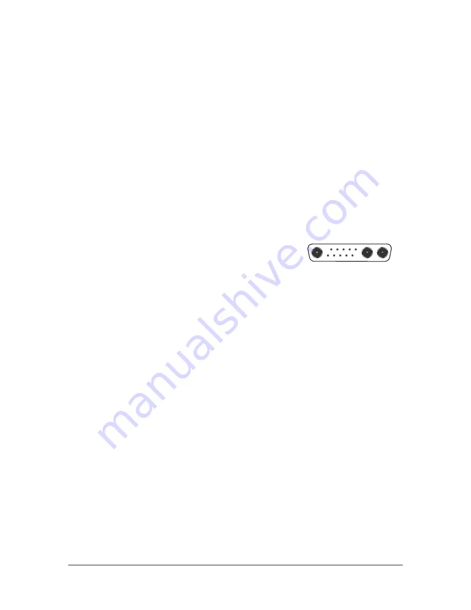
#4 Connect the IN2013 input cable to the computer’s video port.
The input cable is the 3’ long cable permanently attached to the
interface.  Connect this cable to the computer’s video port (see drawing above).

#5 Connect the local computer monitor (if present) to the LOCAL MONITOR OUTPUT on the
IN2013.  
With no local monitor you may have to set the emulation dip switches (see page 7).

#6 Connect the IN2013 output to the display device RGB input.
Using high quality video cables, connect the output BNCs on the IN2013 to the RGB input on
your large screen monitor or data projector.  The interface will automatically set the output sync
format according to the number of cables you have connected to the output:

Cables Connected to BNCs

Output Format

RGB

RGsB

RGBS

RGBS

RGBHV

RGBHV

Cable selection is extremely important to the performance of any high resolution graphics
display system, especially when using long cable runs.  The following Inline cables are available
in a variety of lengths from 6’ to 100’ (longer cables available by special order) and are
recommended for all system connections:

IN7000 Series Standard Resolution Coax Cables - 3, 4 or 5 conductors
IN7100 Series High Resolution Coax Cables - 3, 4, or 5 conductors
IN7200 Series Ultra High Resolution Coax Cables - 3, 4 or 5 conductors

#7 Apply power to the IN2013.
Connect the round connector on the provided power transformer to the power input jack on the
IN2013 (US:  IN9207-1 15VDC / 900mA,  UK/European:  IN9208  15VDC / 1A).  Connect the
power transformer to the A/C power source.

#8 Complete the installation by powering up the computer and computer monitor.
If necessary, adjust the horizontal position control as detailed on page 6.

Summary of Contents for IN2013

Page 1: ...OPERATION MANUAL DEDICATED VIDEO INTERFACE SERIES IN2013 High Resolution Video Interface for 13W3 Workstations...

Page 2: ...7 Internal Controls For Technicians Only 8 12 Opening the IN2013 Case 8 Diagram 2 Internal View 9 Blue and Red Gain Controls 9 Diagram 3 Dip Switches 10 Internal Dip Switches 11 12 SW1 Output Sync Ho...

Page 3: ...t other workstation signals by flipping one or two dip switches Exceptional Video Performance Featuring advanced video amplification circuitry the IN2013 offers video bandwidth in excess of 230 MHz en...

Page 4: ...tation for both the workstation graphics card and the data display device to ensure compatibility Installation steps are listed below and outlined in Diagram 1 on page 5 1 Turn the computer and comput...

Page 5: ...ches see page 7 6 Connect the IN2013 output to the display device RGB input Using high quality video cables connect the output BNCs on the IN2013 to the RGB input on your large screen monitor or data...

Page 6: ...5 RGBHV Cable Power Supply 15V 900mA RGB Input DIAGRAM 1 IN2013 INSTALLATION INPUT HORIZONTAL POSITION LOCAL MONITOR OUTPUT 2013 HIGH RESOLUTION VIDEO INTERFACE FOR 13W3 WORKSTATIONS VERTICAL SYNC HO...

Page 7: ...horizontal position control until the image is centered as desired 3 If the image appears dark or the colors are not properly displayed fine tune the controls on both the display device and the IN2013...

Page 8: ...local monitor If you are not using a local monitor but need to emulate a specific mode locate your workstation type and desired mode in the chart below If you are not sure of the exact mode to select...

Page 9: ...ircuit board PCB to the lower case To assist in reassembly make note of the red ground strap terminal on the center screw 6 Lift the PCB Input Output connector assembly away from the lower case Flip t...

Page 10: ...ale reproduction and color accuracy therefore these controls should only be adjusted by qualified technicians having the necessary test equipment Since the gain pots must be adjusted with power applie...

Page 11: ...10 IN2013 OPERATION MANUAL REV 1 1 12 11 99 1995 INLINE INC...

Page 12: ...another small tool SW1 Output Sync Horizontal Position Control Factory Default Settings 0100001010 These dip switches are normally all covered except for 6 Switch Number Function When Set to ON 1 1 N...

Page 13: ...Switches 8 9 10 on SW3 determine where the interface looks for sync on the input connector and what types of input sync it can accept The factory default setting works with most Sun and SGI workstati...

Page 14: ...ndwidth 230 MHz 3dB 7 volt input signal GENERAL Controls Horizontal Position Video Gain Sharpness Input Computer Select Monitor Emulation Power Supply US IN9207 1 15VDC 900mA UK European IN9208 15VDC...

Page 15: ...d warranty or merchantibility or fitness for any particular purpose all of which are expressly disclaimed The information in this manual has been carefully checked and is believed to be accurate Howev...

Reviews: